Integrated Pet-Mri Scanner

a scanner and integrated technology, applied in the field of positron emission tomography and magnetic resonance imaging (mri) technologies, can solve the problems of poor spatial resolution, serious drawbacks of pet imaging, and poor spatial resolution of images produced by pet scanners, and achieve the effect of reducing electromagnetic interference (emi)

Inactive Publication Date: 2008-09-04
RGT UNIV OF CALIFORNIA
View PDF7 Cites 55 Cited by
  • Summary
  • Abstract
  • Description
  • Claims
  • Application Information

AI Technical Summary

Benefits of technology

[0016]One embodiment of the present invention provides an integrated positron emission tomography (PET)-magnetic resonance imaging (MRI) scanner. This integrated PET-MRI scanner includes a main magnet that generates a magnetic field during an MRI process, wherein the image of the subject is generated in a central region of the magnetic field. It also includes a PET scanner that detects the annihilation photons produced by positron decay within a subject during a PET imaging process, wherein the PET scanner is enclosed by the main magnet. The PET scanner further comprises: (1) at least one ring of scintillators that detect positron-annihilation photons and output light photons in response to the detected positron-annihilation photons, wherein the ring of scintillators is situated in the cent

Problems solved by technology

Unfortunately, PET imaging has a serious drawback: the images produced by a PET scanner typically have relatively poor spatial resolution.
This poor spatial resolution is the result of fundamental physical limitations of the PET process, which involve the mean-free-path of the positrons emitted by the radionuclides (i.e., positron range) and the non-colinearity of the two coincidence photons produced from a positron-annihilation event.
Consequently, for many types of radiotracers used in the PET imaging process, their associated PET images often provide limited anatomical information, making unambiguous localization of the sources of the positron-emissions extremely difficult.
Note that the lack of spatial resolution in the PET images can affect the accuracy in quantifying PET data, which can cause significant underestimation of the actual isotope concentration in structures smaller than 2× the spatial resolution of the PET scanner.
This inaccurate quantification of PET data can subsequently cause problems, for example, in interpreting PET images of tumors where a decrease in uptake of a radiotracer following treatment could indicate tumor shrinkage, a change in the biological function measured by the radiotracer, or both.
However, the task of integrating the two imaging modalities for simultaneous PET and MRI imaging presents many challenges.
This can cause problems when combining PET and MRI, because there is a high probability of interference or interaction between the two systems in the form of electromagnetic interference (EMI).
However, most of the photon detectors and associated electronics contain metal components and their performance is consequently sensitive to magnetic fields

Method used


Image

  • Integrated Pet-Mri Scanner
  • Integrated Pet-Mri Scanner
  • Integrated Pet-Mri Scanner

Examples


Embodiment Construction

[0063]The following description is presented to enable any person skilled in the art to make and use the invention, and is provided in the context of a particular application and its requirements: Various modifications to the disclosed embodiments will be readily apparent to those skilled in the art, and the general principles defined herein may be applied to other embodiments and applications without departing from the spirit and scope of the present invention. Thus, the present invention is not limited to the embodiments shown, but is to be accorded the widest scope consistent with the claims.

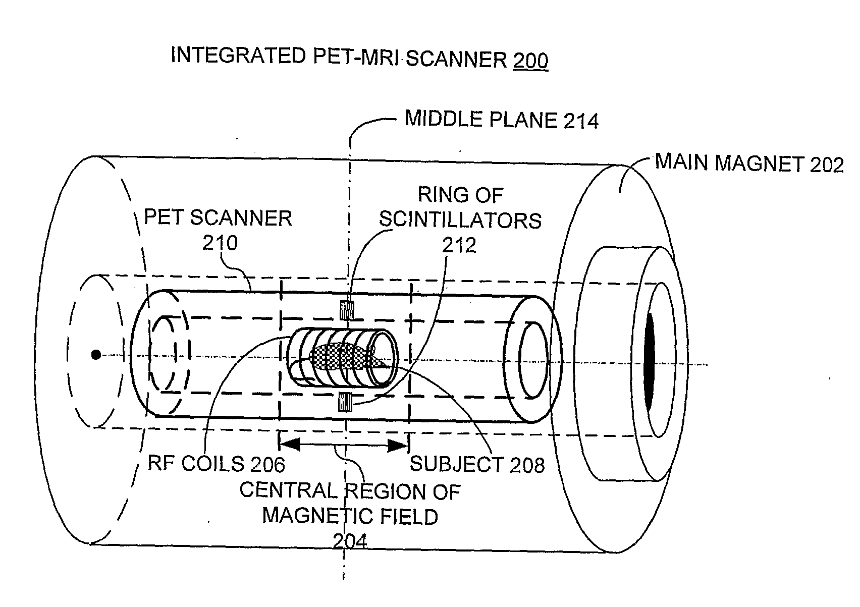
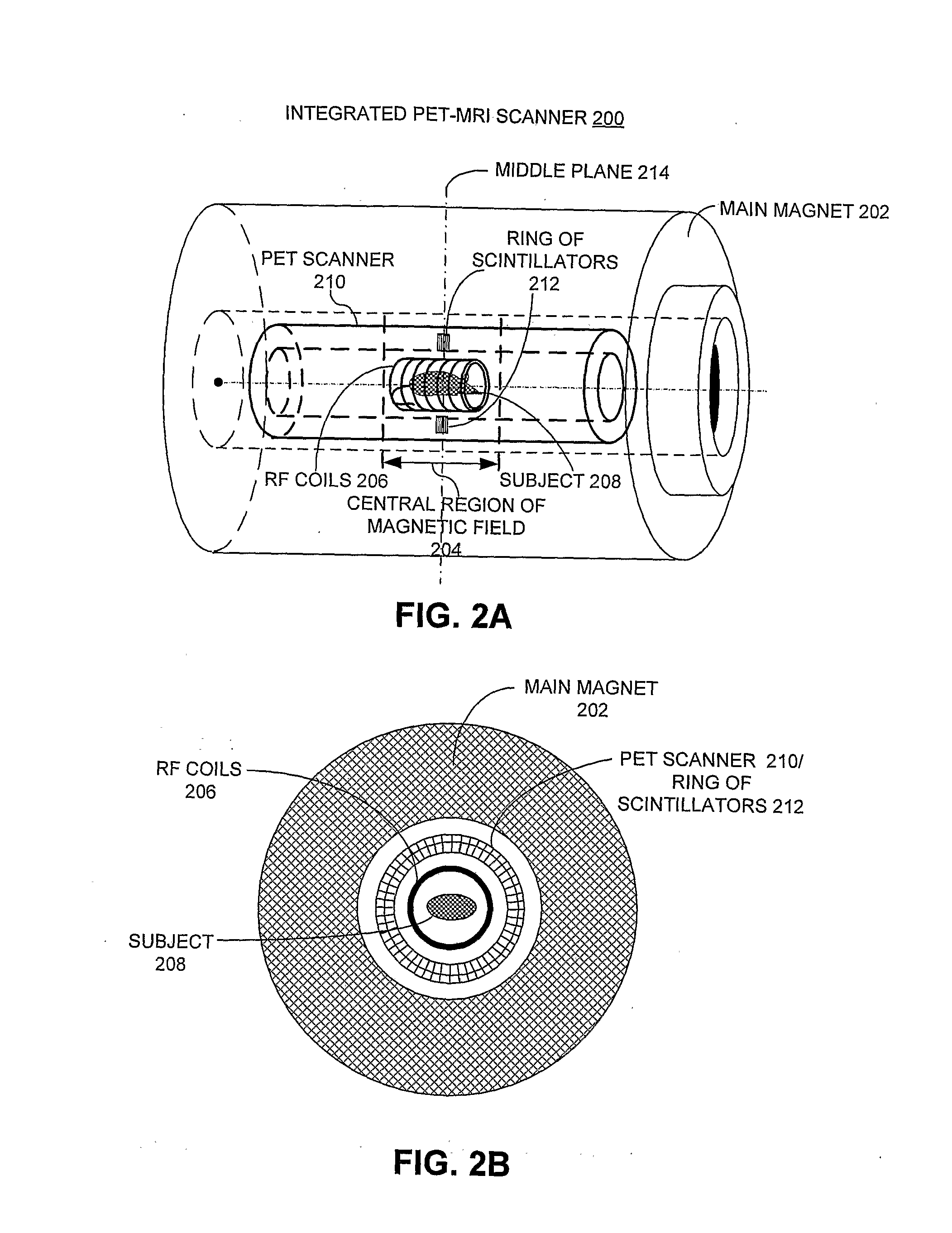
Overall Structure of the Integrated PET-MRI Scanner

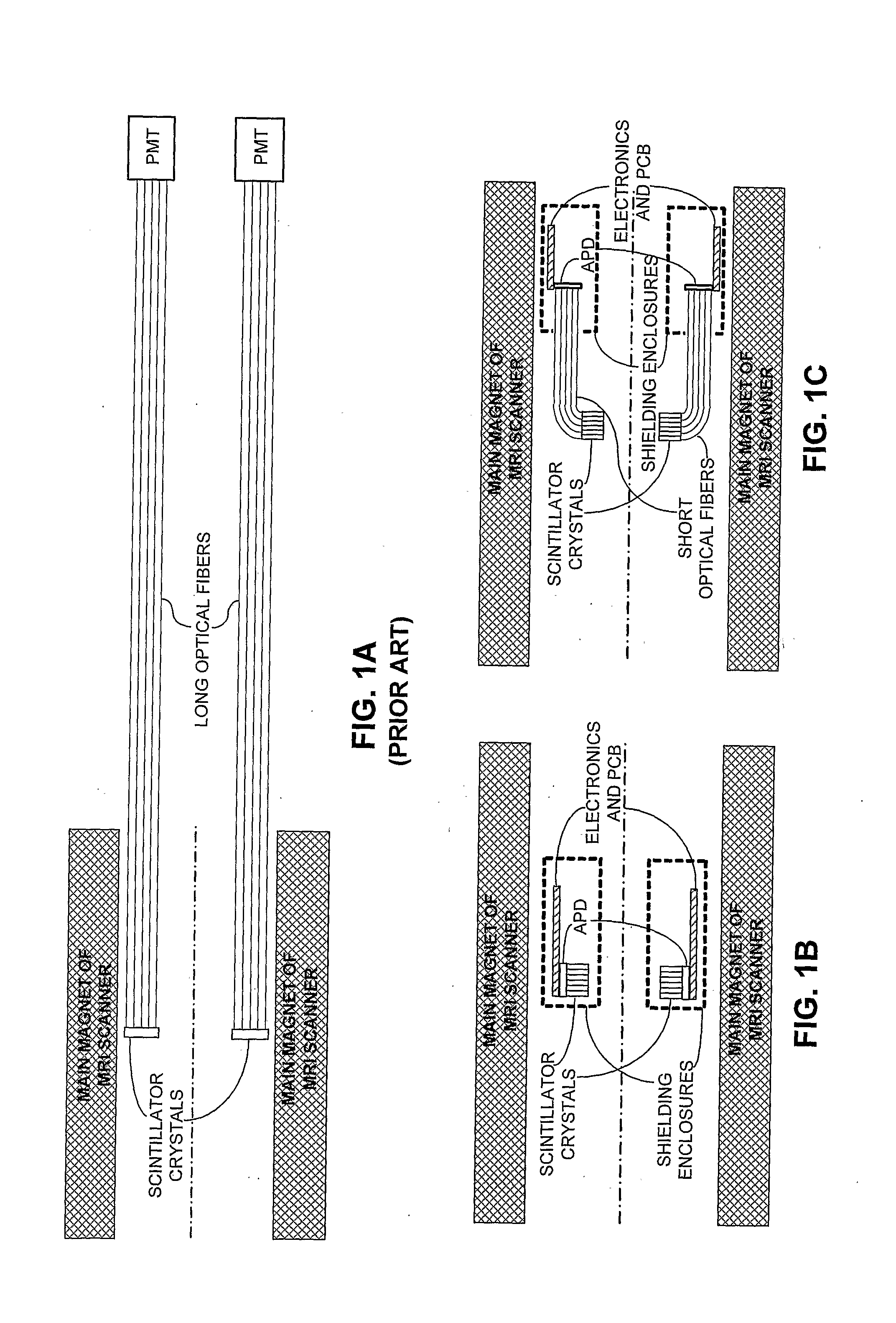
[0064]FIG. 1C illustrates an integrated PET-MRI system which couples scintillator crystals through short optical fibers to avalanche photodetectors (APDs) and associated electronics in accordance with an embodiment of the present invention. In doing so, the electronics and other metal components (e.g., shielding enclosures) of the PET scanner...


PUM


Abstract

One embodiment of the present invention provides an integrated PET-MRI scanner. This integrated scanner includes a main magnet that generates a magnetic field, wherein images of the subject is generated in a central region of the magnetic field. It also includes a PET scanner which is enclosed by the main magnet. The PET scanner further comprises: (1) at least one ring of scintillators, which is situated in the central region of the magnetic field and, (2) one or more photodetectors, which are coupled to the ring of scintillators, so that the one or more photodetectors are outside the central region of the magnetic field. The integrated scanner also includes radio-frequency (RF) coils which are enclosed by the PET scanner. By keeping the photodetectors and associated circuitry outside the central region of the magnetic field, the integrated scanner reduces the electromagnetic interference (EMI) between the PET scanner and the MRI scanner.

Description

BACKGROUND[0001]1. Field of the Invention[0002]The present invention generally relates to positron emission tomography (PET) and magnetic resonance imaging (MRI) technologies. More specifically, the present invention relates to a system and a method that integrates PET and MRI technologies into a combined scanner capable of simultaneous PET and MRI imaging.[0003]2. Related Art[0004]Positron emission tomography (PET) is a powerful molecular imaging modality that uses positron-emitting radionuclides attached to biologically relevant molecules to provide exceptionally sensitive assays of a wide range of biological processes. PET imaging is commonly used to diagnose cancer and to examine the effects of cancer therapy by characterizing biochemical changes in the cancer tissues. PET imaging has also been effective in detecting coronary artery diseases, brain disorders and other diseases.[0005]Unfortunately, PET imaging has a serious drawback: the images produced by a PET scanner typically...

Claims


Application Information

Patent Timeline
IPC IPC(8): A61B5/055
CPCG01R33/481
Inventor CHERRY, SIMONCATANA, CIPRIANPICHLER, BERND J.M.
Owner RGT UNIV OF CALIFORNIA
Why Eureka
Try Eureka