
Method of Surface Treatment and Surface-Treated Article

a surface treatment and article technology, applied in the field of surface treatment of articles, can solve the problems of difficult application difficult to effective decomposition, difficult to apply to a polymeric organic material, etc., and achieve the effect of suppressing the damage of the article and reducing the damag

Inactive Publication Date: 2008-09-04
MITSUBISHI RAYON CO LTD +1
View PDF8 Cites 17 Cited by
  • Summary
  • Abstract
  • Description
  • Claims
  • Application Information

AI Technical Summary

Benefits of technology

[0025]According to the method for surface-treatment of the present invention, the organic substances which adheres to an article can be decomposed or removed without scattering in the atmosphere and damage of the article can be suppressed. Furthermore, the surface of the article can be etched with suppressing damage of the article.
[0026]The article obtained by the method for surface-treatment of the present invention is highly etched or washed, and has little damage.

Problems solved by technology

According to the method (I), there are problems that (1) organic substances existed on the surface of a heat-resistant article such as an inorganic material can be decomposed or removed by plasma; however, the decomposed substances or unreacted organic substances float in the atmosphere; and (2) a high-energy plasma gas can be generated; however, it becomes difficult to apply to a polymeric organic material since the surface temperature of an article becomes extremely high.
According to the method (II), there are problems that (1) organic substances dispersed in the liquid can be decomposed; however, it is uncertain whether the method (II) can be applied for removing the organic substances adhered to the surface of an article; and (2) it is difficult to apply to a polymeric organic material since the surface temperature of the article becomes high, as well as the method (I), even if the plasma in the bubbles are contacted the article for decomposing the organic substances.
According to the method (III), there are problems that (1) organic substances dispersed in the liquid can be decomposed; however, it is uncertain whether the method (II) can be applied for removing the organic substances adhered to the surface of an article, as well as the method (II); and (2) since a plasma can maintain a plasma state for only a short time, it is difficult to effective decomposition when the frequency of contacting bubbles which is in plasma state (hereinafter, referred to plasma bubbles) and the organic substances to be decomposed is low.
However, as described in Patent Document 3 of the method (II), the plasma bubbles have high temperature of approximately 5000 K; on the other hand, the polymeric organic material does not usually have sufficient heat resistance which can withstand such high temperature.
It is difficult to apply the fiber using such material to the plasma bubbles.
When such material having inferior heat resistance is used, it can be expected that the fiber itself will be destroyed rather than that the portion consisting of alternate lands and grooves will be imparted to the surface of the fiber.
Furthermore, Patent Document 10 discloses a carbon fiber as an example; however, the carbon fiber is extremely thin and a part of the fiber which contacted the plasma bubbles being partially high temperature is excessively graphitized by heat though the degree of graphitization changes in accordance with the pattern of crinkles of the surface of the fiber, the level of graphite structure of the surface of the fiber, and the level of flame resistance.
Therefore, it is considered that the fiber becomes brittle locally and mechanical properties of the fiber decreases as a whole.
When the material having inferior heat resistance is used, Patent Document 10 does not disclose whether the fiber can be washed without changing the pattern of the surface thereof.

Method used


Image

  • Method of Surface Treatment and Surface-Treated Article
  • Method of Surface Treatment and Surface-Treated Article
  • Method of Surface Treatment and Surface-Treated Article

Examples


example 1

[0122]A water-purifying device for home use (trade name: Cleansui 02) manufactured by Mitsubishi Rayon Co., Ltd. was prepared. In a filtration cartridge of the water-purifying device, a hollow fiber membrane (the contact angel of water of a raw material which is treated so as to be a hydrophilic one (25° C.)=55°) made of polyethylene which was treated so as to be a hydrophilic one was used. The hollow fiber membrane is a hollow fiber membrane having inner diameter of 270 μm and thickness of the membrane of 55 μm manufactured by Mitsubishi Rayon Co., Ltd. In the hollow fiber membrane, fibrils made of polyethylene oriented in the direction of the fiber of the hollow fiber membrane, the hollow fiber membrane had a pore structure being a slit form in which many fibrils were piled up in the direction of the thickness of the membrane.

[0123]When the water-purifying device was set to a faucet of water supply in home, and water from water supply (Mikasa-cho, Iwakuni-shi, Yamaguchi-ken, Japan...

example 2

[0129]The same plasma generating device as Example 1 was used. The sample for experiment was soaked in a container filled with water and the samples were fixed with supports in the vicinity of the electrode. Except using an ethylene / vinyl alcohol copolymer film (hereinafter, may be referred to EVAL film) shown in Table 9 as a sample, water vapor bubble plasma was generated and the plasma was contacted to the sample for 3 minutes at the same condition as Example 1. Each film had the contact angle to water before contacting to plasma being within 64 to 71° and showed hydrophilicity. These films stood the heat of water vapor bubble plasma and maintained their original forms.

TABLE 9Plasma durability6)(Gas phase of reactiondevice: atmosphericpressure)7)Measurement of contact angle of EVAL filmHaving durability8):EVAL filmgoodEthylene1)θ / 22)θ3)RH5)Not havingSample(mol %)(degree)(degree)T4) (° C.)(% RH)durability9): not goodD29082932.264.425.437GoodDC3203F3233.667.225.538GoodET38033834.669...

example 3

[0132]Nafion® 112 and Nafion® 1035 membranes manufactured by DuPont were soaked in ion-exchanged water at 25° C. for 5 minutes to swell the membranes, and the swollen membranes were taken out and the contact angles thereof were measured. The contact angles were shown in Table 10. Nafion® 112 and Nafion® 1035 shown in Table 10 were used as samples for plasma treatment.

[0133]The same plasma generating device as Example 1 was used. The samples were soaked in a container filled with water and the samples were fixed with supports in the vicinity of the electrode. Subsequently, water vapor bubble plasma was generated at the same conditions as Example 1, and the plasma was contacted to the samples for 3 minutes. As shown in Table 10, both swollen Nafion® 112 and Nafion® 1035 membranes stood the heat of the water vapor bubble plasma, and their original forms were maintained.

TABLE 10Plasma durability(Gas phase of reactiondevice: atmosphericpressure)Having durability: goodθ / 2θTRHNot having du...


PUM

PropertyMeasurementUnit
contact angleaaaaaaaaaa
temperatureaaaaaaaaaa
frequencyaaaaaaaaaa

Abstract

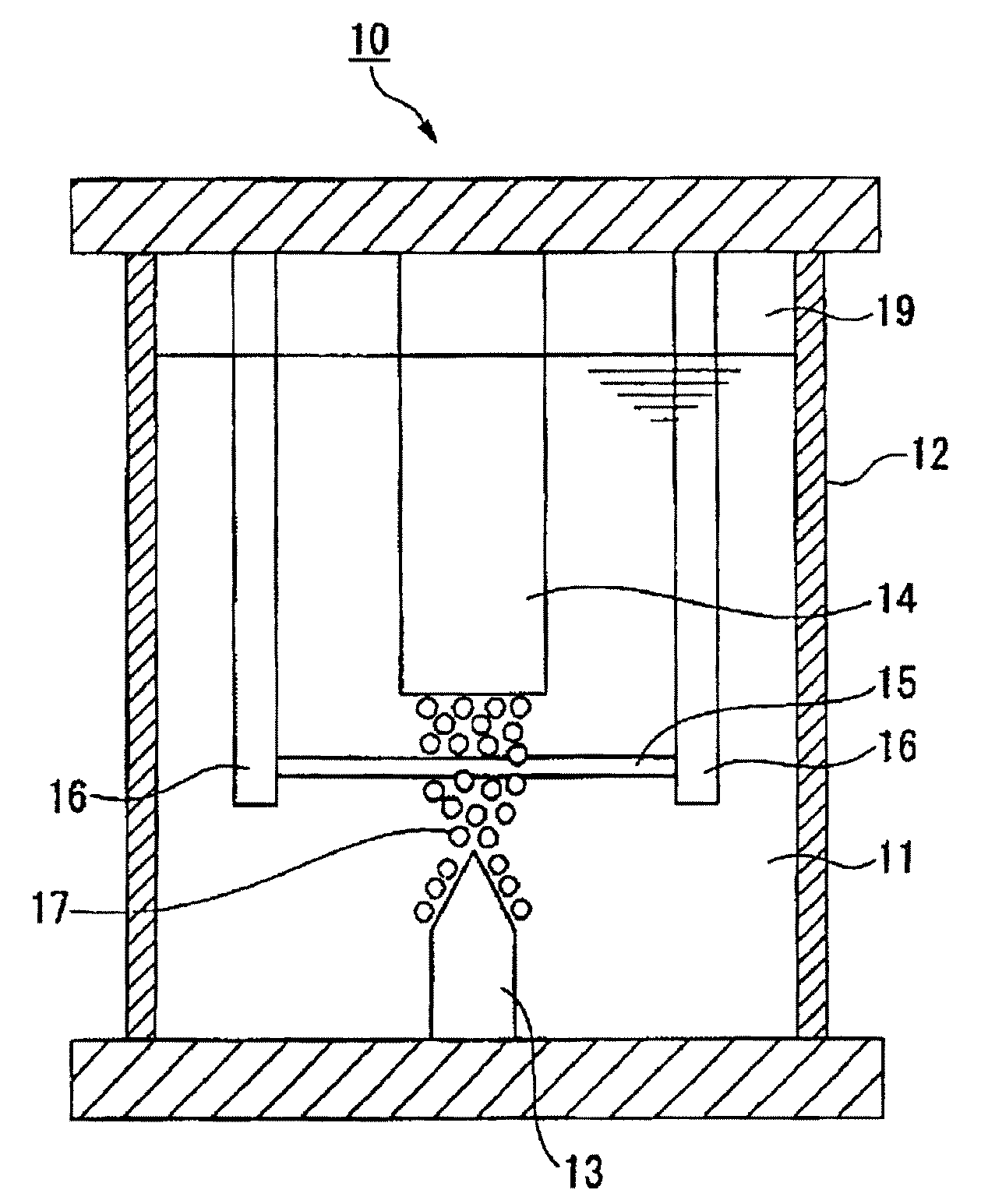
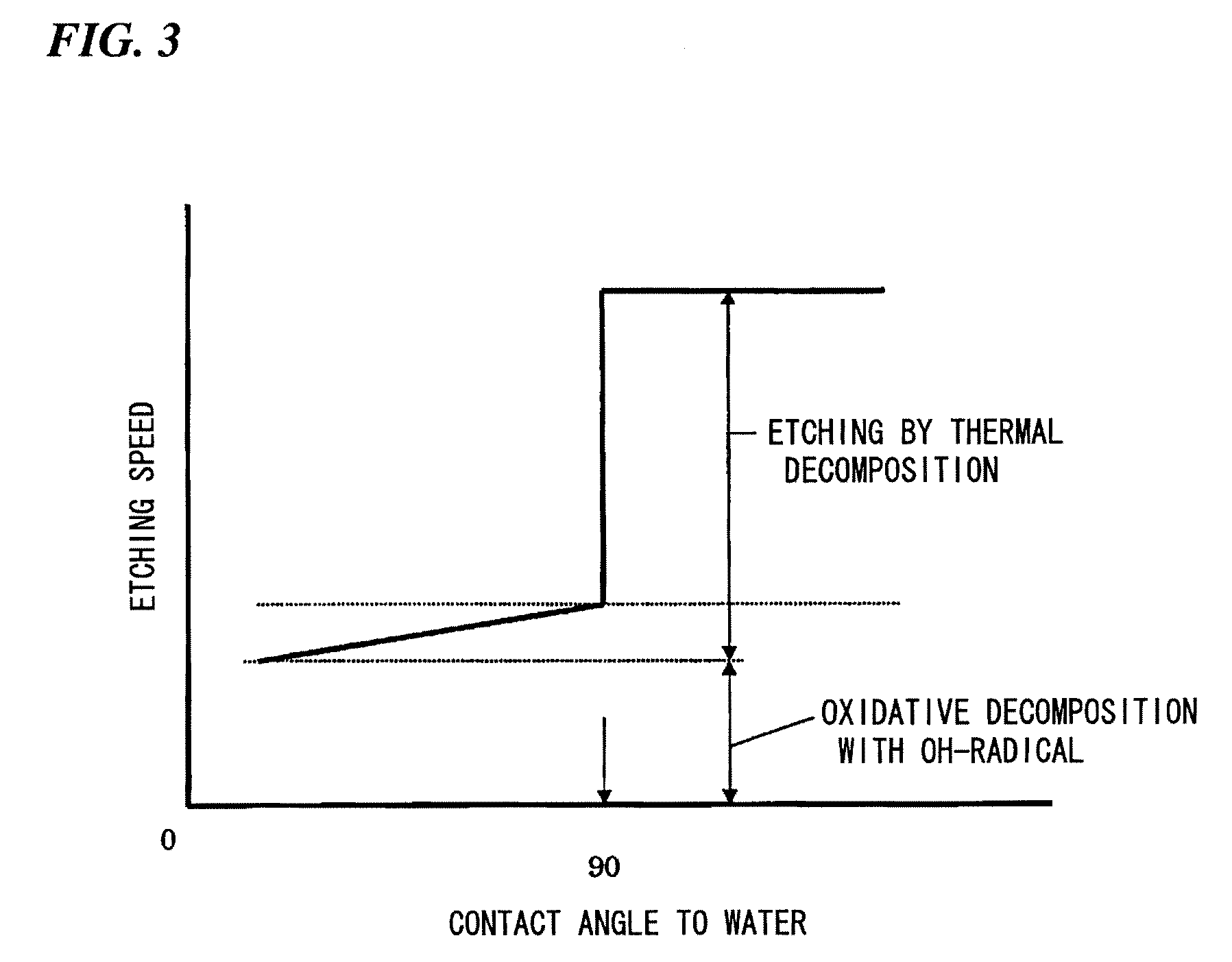
Plasma generated in water vapor bubbles present in a water-containing liquid is brought into contact, in the liquid, with an article having a contact angle with water of 90° or less. The plasma is contacted with an organic substance adhering to the article to thereby remove the organic substance from the article. By bringing the plasma into contact with the article, the surface of the article is etched without breaking the article. The article may comprise a material composed of both a hydrophobic part having a contact angle with water exceeding 90° and a hydrophilic part having a contact angle with water of 90° or less. In this case only the hydrophobic part is etched by bringing the plasma into contact with the article.

Description

TECHNICAL FIELD[0001]The present invention relates to a method of surface treatment of articles having a hydrophilic surface, and a surface-treated article by the method.[0002]Priority is claimed on Japanese Patent Application No. 2005-089631 filed on Mar. 25, 2005, the content of which is incorporated herein by reference.BACKGROUND ART[0003]As a method for decomposing or removing organic substances by a plasma, for example, the following method is known.[0004](I) A method for removing organic substances which adhere to the surface of a substrate such as a silicon wafer or a glass substrate for liquid crystal by converting an oxygen gas or an argon gas into plasma under the atmospheric pressure, and spraying the plasma to the surface of the substrate has been proposed (see Patent Documents 1 and 2). Furthermore, an atmospheric pressure plasma surface treatment device has been put in practical use by this method and has been already manufactured.[0005](II) A method comprising irradia...

Claims


Application Information

Patent Timeline
Patent Type & Authority Applications(United States)
IPC IPC(8): C23F1/02
CPCA61L2/14H01L21/02054B01D2321/2075B01D65/02B01J19/08A62D3/00B01D67/00B08B7/00C23G5/00H01L21/02315H01L21/3065H01J37/32
Inventor UENISHI, MASAMOTONOMURA, SHINFUKUTOYOTA, HIROMICHI
Owner MITSUBISHI RAYON CO LTD
Learn More