
Rotating electrical machine for vehicle

a technology of electrical machines and vehicles, applied in the direction of electrical apparatus, dynamo-electric machines, supports/enclosements/casings, etc., can solve the problems of liable disconnection of electric wires or the like, and achieve the suppression of dust or the like, the increase of the holding strength of the harness clamp, and the suppression of damage to the protective cover and the disconnection of electric wires.

Active Publication Date: 2014-07-24
MITSUBISHI ELECTRIC CORP
View PDF4 Cites 3 Cited by
  • Summary
  • Abstract
  • Description
  • Claims
  • Application Information

AI Technical Summary

Benefits of technology

The present invention provides a reliable and secure way to attach a rectifier to a casing and to fix a harness clamp to the casing, while also preventing vibration and damage to the protective cover. The invention also helps to prevent water and dust from entering the protective cover.

Problems solved by technology

When those electric wires are excessively long, the electric wires vibrate due to vibration of an engine or the like, with the result that disconnection of the electric wires or the like is liable to occur.

Method used


Image

  • Rotating electrical machine for vehicle
  • Rotating electrical machine for vehicle
  • Rotating electrical machine for vehicle

Examples


first embodiment

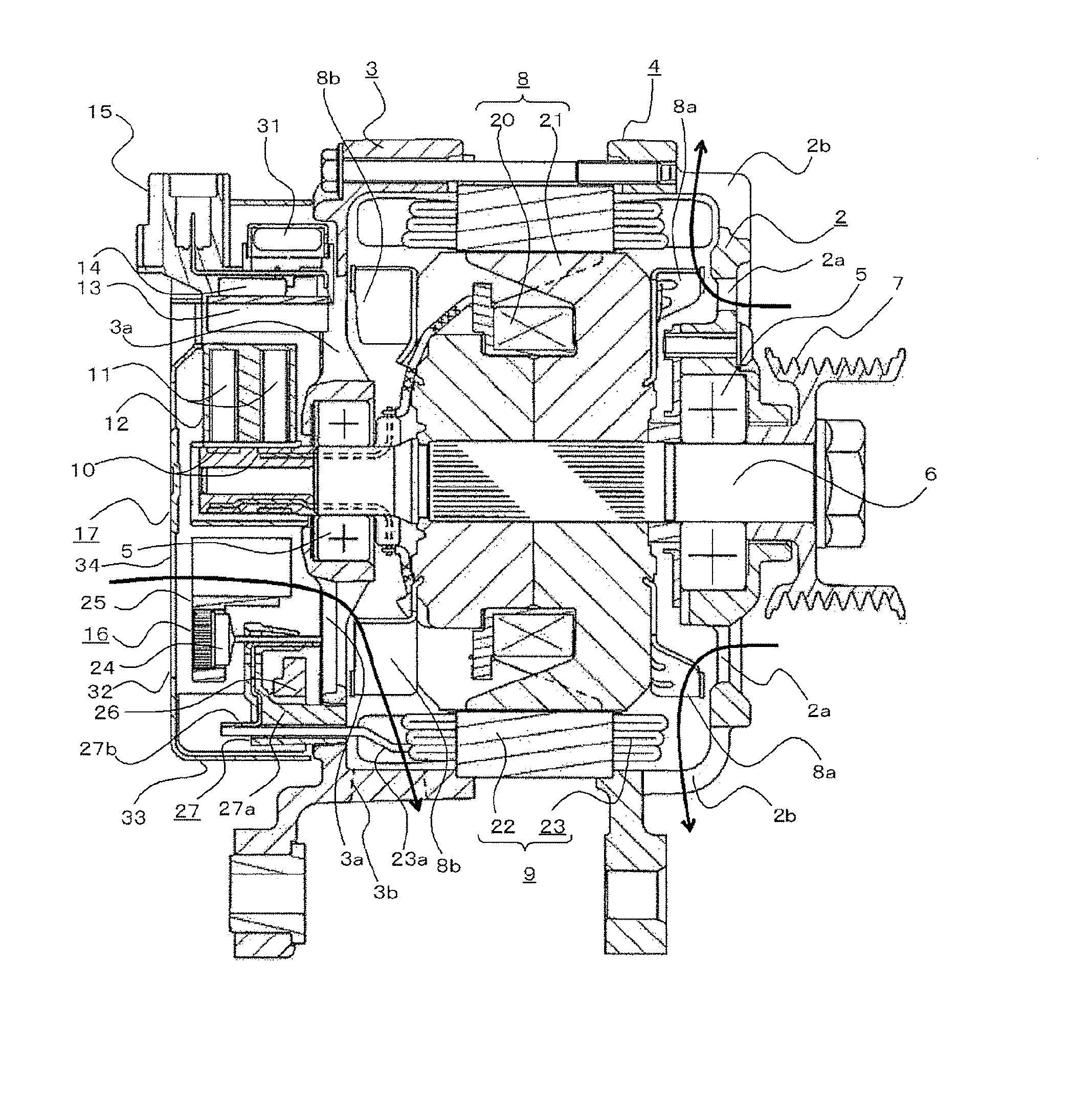
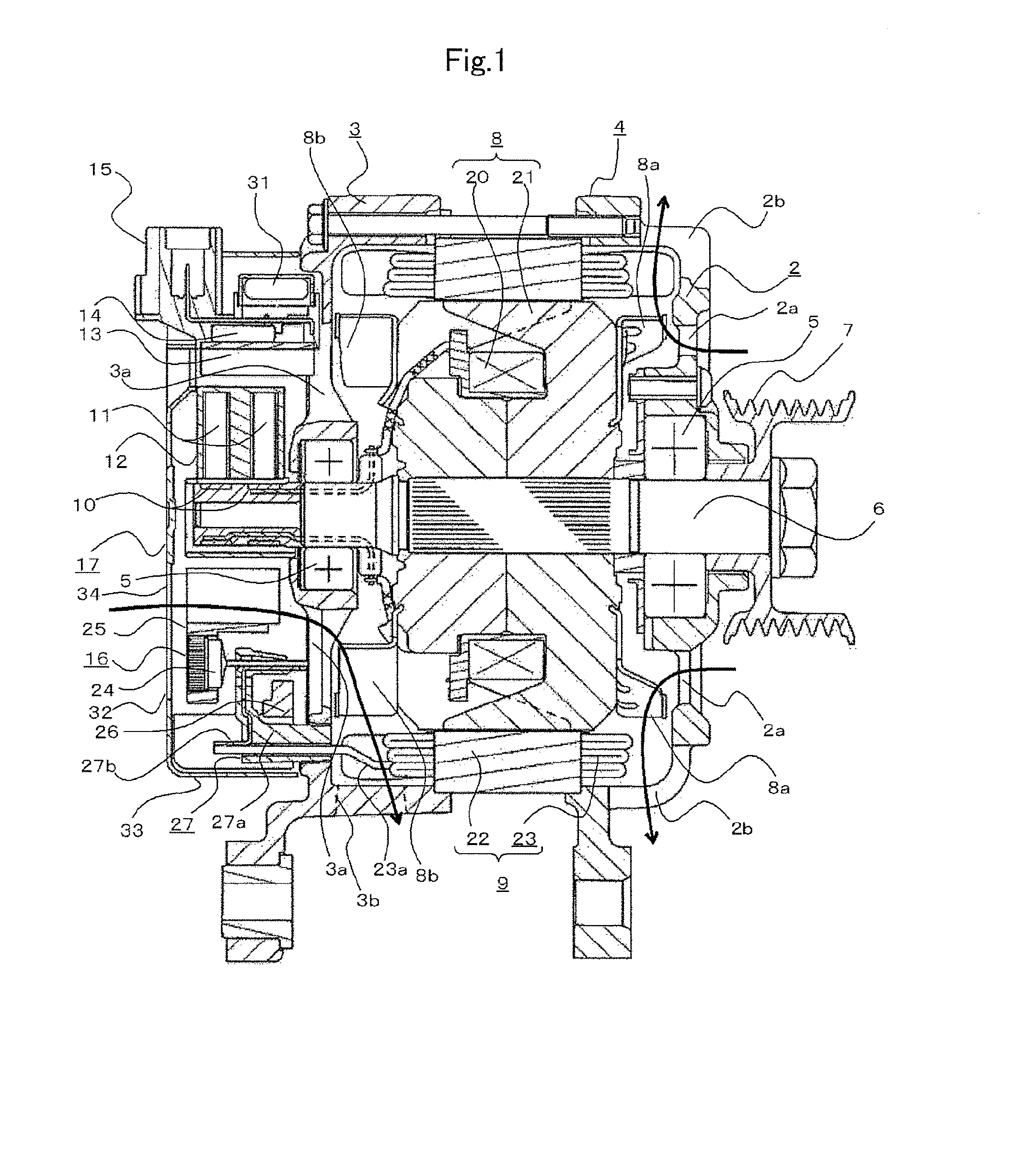
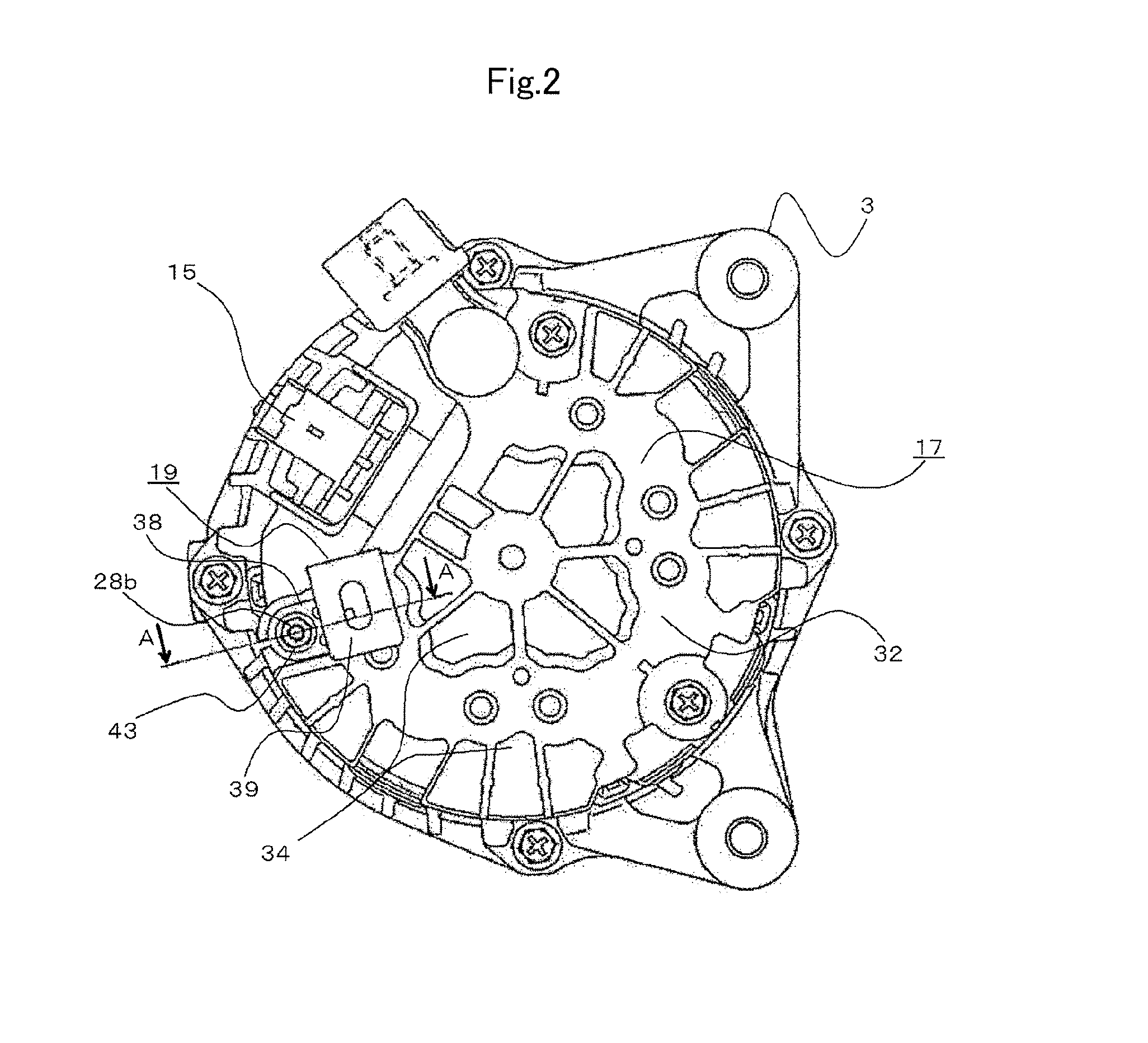
[0020]FIG. 1 is a sectional view illustrating an entire AC generator for a vehicle according to a first embodiment of the present invention. FIG. 2 is a plan view of the AC generator for a vehicle in FIG. 1 as seen from a protective cover side. FIG. 3 is a sectional view of the AC generator for a vehicle taken along the arrow A-A in FIG. 2. FIG. 4 is a sectional view of a main part of the AC generator for a vehicle, for illustrating a state before a fitting is mounted according to the first embodiment of the present invention. FIG. 5 is a sectional view of a main part of the AC generator for a vehicle, for illustrating a state in which electric wires are fixed according to the first embodiment of the present invention. FIG. 6 are views illustrating the structure of the fitting according to the first embodiment of the present invention, in which FIG. 6(a) is a top view, and FIG. 6(b) is a side view. FIG. 7 is an enlarged sectional view of a main part of the AC generator for a vehicle...


PUM


Abstract

A rotating electrical machine for a vehicle includes a protective cover including a protruding portion projected to an opening side from a circumferential edge portion of a through hole formed in a bottom portion, a stud bolt that is inserted into the through hole to fix a rectifier to a portion of a casing at a position on one side in an axial direction, a mold resin including a projecting portion projected toward the protective cover, for electrically insulating the rectifier and the stud bolt from each other, and a fitting fixed to an extending portion of the stud bolt that extends from the through hole. A harness clamp is held by the fitting, and the projecting portion and the protruding portion are arranged at a position so that the projecting portion and the protruding portion are overlapped with each other in the axial direction of the stud bolt.

Description

TECHNICAL FIELD[0001]The present invention relates to a rotating electrical machine for a vehicle, such as an alternating current (AC) generator for a vehicle, and more particularly, to a holding structure for electric wires arranged around a rotating electrical machine for a vehicle, which is mounted in a vehicle.BACKGROUND ART[0002]A great number of electric wires are arranged around an AC generator for a vehicle, which is mounted in a vehicle. When those electric wires are excessively long, the electric wires vibrate due to vibration of an engine or the like, with the result that disconnection of the electric wires or the like is liable to occur. Therefore, the electric wires are partially fixed to a vehicle body, the AC generator for a vehicle, or the like.[0003]Further, in a related art AC generator for a vehicle, a rectifier and the like are fixed to an outer side of a rear-side frame, and a rear cover made of a resin is fixed to the rear-side frame so as to cover the rectifie...

Claims


Application Information

Patent Timeline
IPC IPC(8): H02K9/06
CPCH02K9/06H02K5/10H02K11/05H02K5/225
Inventor KIMATA, HIROTAKATANAKA, KAZUNORI
Owner MITSUBISHI ELECTRIC CORP
Learn More