
Wire harness

a wire harness and wire technology, applied in the direction of electrical/fluid circuits, electrical apparatus, vehicle components, etc., can solve the problems of promoting damage and possibly damaging and achieve the effect of suppressing damage to the electrically conductive path

Active Publication Date: 2017-10-03
YAZAKI CORP
View PDF31 Cites 3 Cited by
  • Summary
  • Abstract
  • Description
  • Claims
  • Application Information

AI Technical Summary

Benefits of technology

This patent is about a wire harness that prevents damage to the electrical wires it contains. The wire harness stops the wires from rubbing against the sheath in which they are placed, which could cause damage. This feature helps protect the wires and ensures they are not damaged during use.

Problems solved by technology

According to a related art, in a wire harness disclosed in the Patent Literature 1, there is an inconvenience that an electrically conductive path accommodated in a tubular sheath member has a fear which the electrically conductive path may be possibly damaged.
Further, since dust or sand enters the sheath member by a secular use, a problem arises that the dust or sand causes the damage to be promoted due to an abrasion.

Method used


Image

  • Wire harness
  • Wire harness
  • Wire harness

Examples


Embodiment Construction

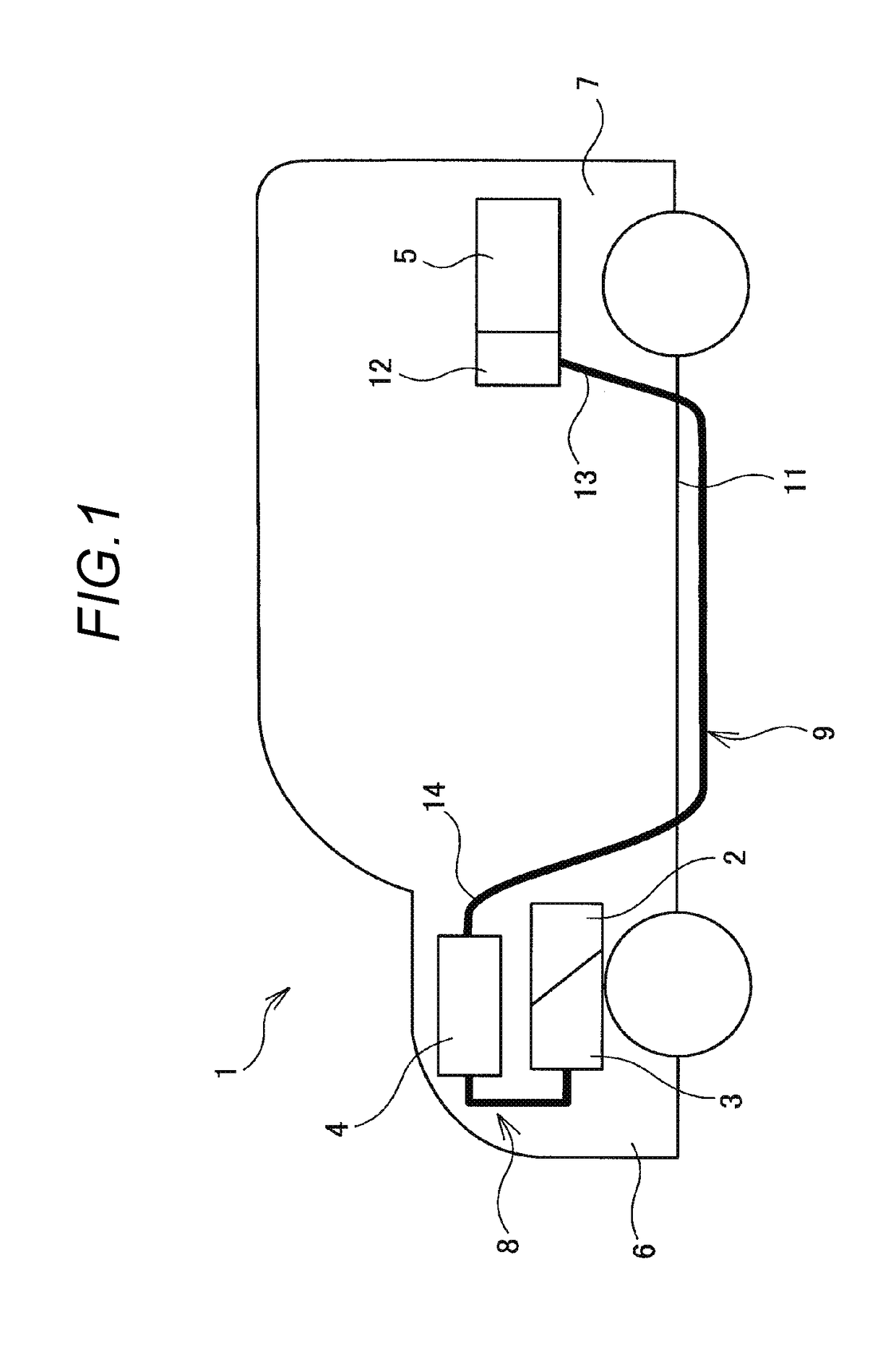
[0020]FIG. 1 is a schematic view showing an arranged state of a wire harness 9 according to the present embodiment. The wire harness 9 according to the present embodiment is used for a hybrid motor vehicle 1 and arranged in a prescribed position of the hybrid motor vehicle 1.

[0021]The hybrid motor vehicle 1 is a vehicle which is driven by combining together two powers of an engine 2 and a motor unit 3. To the motor unit 3, an electric power from a battery (a battery pack) is supplied through an inverter unit 4. The engine 2, the motor unit 3 and the inverter unit 4 are mounted on an engine room 6 in the vicinity of front wheels. Further, the battery 5 is mounted on a rear part 7 of the motor vehicle in the vicinity of rear wheels, however, the battery may be mounted in an interior of the motor vehicle located in a rear part of the engine room 6.

[0022]The motor unit 3 and the inverter unit 4 are connected together by a wire harness 8 for a high voltage. Further, the battery 5 and the...


PUM


Abstract

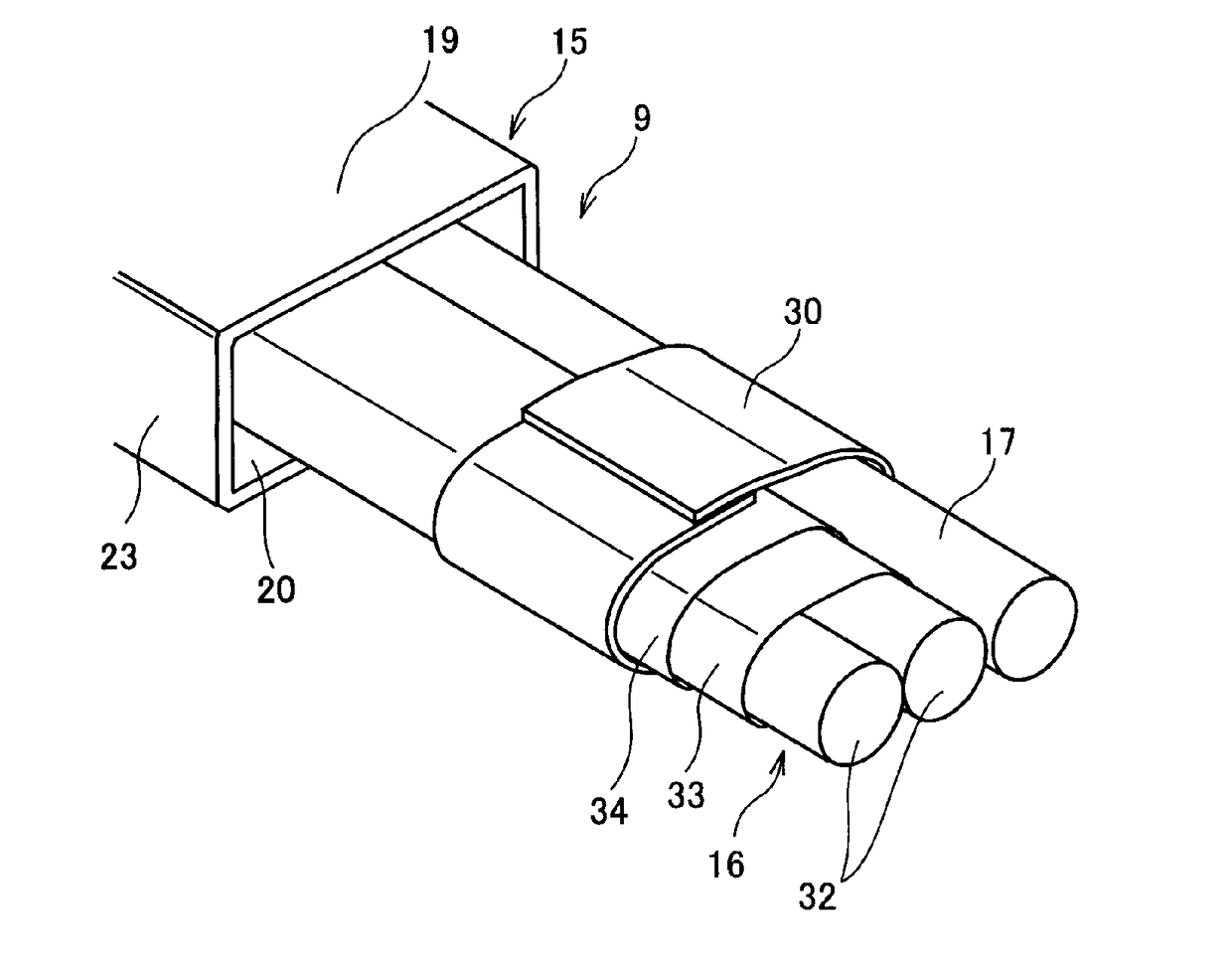
A wire harness is provided with an electrically conductive path, a tubular sheath member which accommodates the electrically conductive path in an inner part, and a sheet member positioned between at least a part of a circumferential direction of the electrically conductive path and an inner peripheral surface of the sheath member. The sheet member may be wound on the electrically conductive path so as to cover an entire area in the circumferential direction. The sheet member may be intermittently arranged in an axial direction of a tube of the sheath member.

Description

CROSS REFERENCE TO RELATED APPLICATIONS[0001]This application is a continuation of PCT application No. PCT / JP2014 / 068364, which was filed on Jul. 9, 2014 based on Japanese Patent Application (No. 2013-146318) filed on Jul. 12, 2013, the contents of which are incorporated herein by reference.BACKGROUND OF THE INVENTION[0002]Field of the Invention[0003]The present invention relates to a wire harness.[0004]Description of Related Art[0005]Usually, a wire harness is known which electrically connects together high voltage devices mounted on a hybrid motor vehicle or an electric vehicle. The wire harness is formed with an electrically conductive path and a sheath member which accommodates the electrically conductive path therein as main members. The sheath member is formed with a hollow tubular member, which is desired to be hardly bent even when a bending stress is applied thereto by considering a protection of the electrically conductive path, a regulation of the path and a working prope...

Claims


Application Information

Patent Timeline
Patent Type & Authority Patents(United States)
IPC IPC(8): B60R16/02H02G3/04H02G3/32
CPCB60R16/0207B60R16/0215H02G3/0487H02G3/0468H02G3/32H02G3/0481
Inventor INAO, SHINICHIOGA, TATSUYAADACHI, HIDEOMI
Owner YAZAKI CORP
Learn More