
Hard Material Layer

Inactive Publication Date: 2008-08-14
OERLIKON TRADING AG TRUEBBACH
View PDF7 Cites 28 Cited by
  • Summary
  • Abstract
  • Description
  • Claims
  • Application Information

AI Technical Summary

Benefits of technology

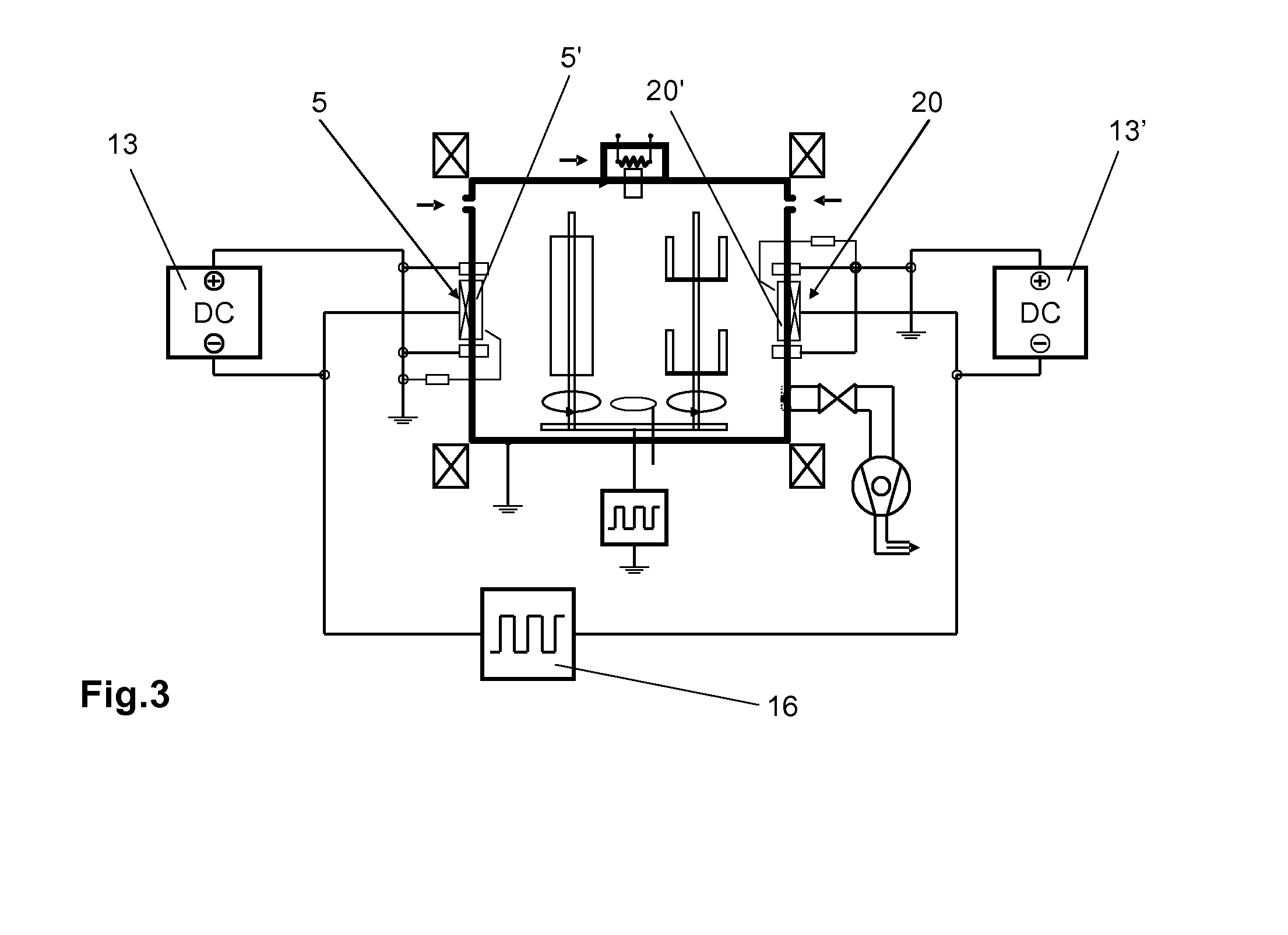
[0024]An especially preferred embodiment comprises that both electrodes are the cathodes of one arc evaporator source each and that each of these arc evaporator sources by itself is connected directly to a DC power supply for the purpose of maintaining a holding current and wherein the two cathodes are connected to a single pulsed power supply such that the arcs, or the arc discharges, of the two sources are not extinguished in operation. In this configuration, consequently, only one pulsed power supply is required since this supply is interconnected directly between the two cathodes of the arc evaporators. Apart from the high degree of ionization and the good controllability of the process, high efficiency of the configuration also results. Between these two electrodes and the pulse discharge gap additionally generated thereby, compared to this discharge gap, a bipolar pulse forms electrically from negative and positive components, whereby the entire period duration of this fed AC voltage can be utilized for the process. In fact, no unused pulse pauses are generated and the negative as well as also the positive pulses without interruption contribute overall to the process. The deposition rate can thereby be additionally increased without having to employ additional expensive pulsed power supplies. This configuration with two arc evaporator sources is especially suited for the deposition of layers from a metallic target utilizing reactive gas. With this configuration it becomes even possible to omit entirely supporting inert gases, such as argon, and it is possible to work with pure reactive gas, even unexpectedly with pure oxygen. Through the high degree of ionization attainable therewith of the vaporized material as well as also of the reactive gas, such as for example oxygen, nonconducting layers with high quality are generated which nearly reach the quality of the bulk material. The process runs very stably and herein the splatter formation is, unexpectedly, also reduced or entirely avoided. However, said advantages can also be attained by using other sources as the second electrode, such as, for example, a bias electrode or a low-voltage arc evaporator crucible, although said advantageous effects are not attained to the same degree as in the implementation of the configuration with two arc evaporators.
[0025]The present application claims priority of the two cited preceding applications CH 00518 / 05 and 01289 / 05 which substantially disclose a first approach to a solution for the present problem formation of the deposition of electrically nonconducting oxidic layers. The invention introduced in the present patent application represents a further development regarding the conduction of the process and the application. These two applications are consequently an integrating component of the present application.
[0026]The various features of novelty which characterize the invention are pointed out with particularity in the claims annexed to and forming a part of this disclosure and are entirely based on the Switzerland priority application no. 518 / 05, filed Mar. 24, 2005, and Switzerland priority application no. 1289 / 05, filed Aug. 3, 2005.

Problems solved by technology

A significant disadvantage with these sources comprises that in the proximity of the cathode spot very rapidly proceeding melting occurs on the target surface, whereby drops are formed, so-called droplets, which are hurled away as splatters and subsequently condense on the workpiece and consequently have an undesirable effect on the layer properties.
With high requirements made of the layer quality, layers generated thusly, can often not be commercially applied.
The use of reactive gases for the deposition of compounds from a metallic target in a reactive plasma was until now limited to the production only of electrically conductive layers.
In the production of electrically nonconducting, thus dielectric layers, such as for example of oxides using oxygen as the reactive gas, the problem of splatter formation is intensified.
The re-coating of the target surfaces of the arc evaporator and of the counterelectrodes, such as the anodes and also other parts of the vacuum process installation, with a non-conducting layer leads to entirely unstable conditions and even to the quenching of the arc.
In this case the latter would have to be repeatedly newly ignited or it would thereby become entirely impossible to conduct the process.
In the reactive coating by means of arc evaporator source there is a lack of reactivity and process stability, especially in the production of insulating layers.
Working with high frequency, such as is the case during sputtering, has so far failed due to the lacking technique of being able to operate high-power supplies with high frequencies.
In oxidized target surfaces a renewed igniting with mechanical contact and by means of DC supplies is not possible.
The actual problem in reactive arc evaporation are the coatings with insulating layers on the target and the anode, or on the coating chamber connected as the anode.
In the course of their formation, these insulating coatings increase the burn voltage of the spark discharge, lead to increased splatters and sparkovers, an unstable process, which ends in an interruption of the spark discharge.
A highly diluted reactive gas (for example argon / oxygen mixture) can delay the accretion on the target, however it cannot solve the fundamental problem of process instability.
While the proposal according to U.S. Pat. No. 5,103,766 of alternately operating the cathode and the anode with renewed ignition each time results in process stability, it does however lead to increased splatters.
The method most frequently mentioned is dual magnetron sputtering, which in this application entails great disadvantages with respect to process reliability and costs.
However, this does not necessarily make the process less expensive and faster.
Until now it also did not appear possible to be able to produce satisfactorily alpha aluminum oxide layers by means of arc evaporation.
With respect to prior art the following disadvantages are summarized, in particular regarding the production of oxidic layers with reactive process:1. Stable conduction of the process is not possible for the deposition of insulating layers, if there is no spatial separation between arc evaporator cathode or anode of the arc discharge and the substrate region with reactive gas inlet.
2. There is no fundamental solution of the problematic of splatters: conglomerates (splatters) are not fully through-reacted, wherein metallic components occur in the layer, increased roughness of the layer surface is generated and the constancy of the layer composition and the stoichiometry is disturbed.3. Insufficient possibilities for realizing low-temperature processes, since insufficiently the thermal loading of the substrate is too high for the production of oxides with high-temperature phases.4. The production of flat graduated intermediate layers for insulating layers has so far not been possible by means of arc evaporation.
These conglomerates impinge as such onto the substrate and result in rough layers, and it has not been possible fully to react-through the splatters.
Avoidance or fragmentation of these splatters was so far not successful, especially not for reactive coating processes.
In these, on the cathode of the arc evaporator source, for example in oxygen atmosphere, additionally a thin oxide layer forms, which tends to increased splatter formation.

Method used


Image

  • Hard Material Layer
  • Hard Material Layer
  • Hard Material Layer

Examples


example 2

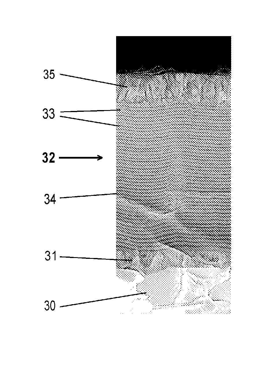
[0089]Coating of workpieces 30, such as cutting tools, preferably indexable inserts, with an Al—Cr—O hard material layer system 32 and Cr—N intermediate layer 31 by means of DPAE (Dual Pulsed Arc Evaporator)

[0090]Steps 1 to and including 5 analogous to Example 1.

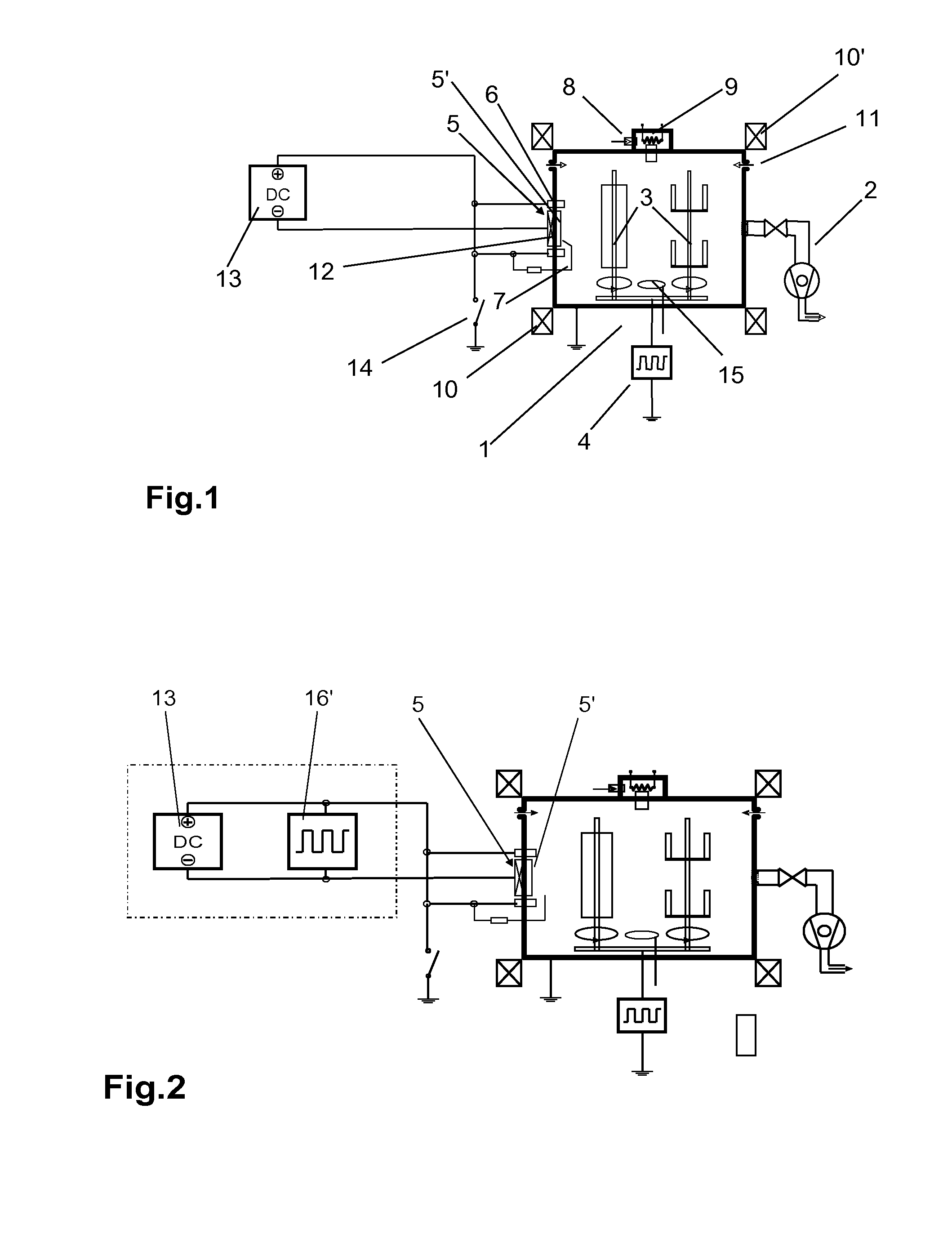
[0091]6. Starting the coating with the intermediate layer (approximately 15 min) AlCrN intermediate layer 300 nm by means of spark evaporation (target material AlCr (50%, 50%), source current 180 A, N2 800 sccm, with bipolar bias of −180 V (36 μs negative, 4 μs positive).[0092]The coating can take place with and without low-voltage arc.[0093]Up to this point the method follows prior art such as is shown for example in FIG. 1.

[0094]7. Transition to functional layer 32 (approximately 5 min) In the transition to the functional layer 32 proper, the nitrogen is ramped down from 800 sccm to approximately 600 sccm and subsequently an oxygen flow of 400 sccm is switched on. The nitrogen flow is now switched off.

[0095]8. Coating with...


PUM

PropertyMeasurementUnit
currentsaaaaaaaaaa
pulse frequenciesaaaaaaaaaa
Pulse currentsaaaaaaaaaa

Abstract

A hard material layer is deposited on a workpiece as a functional layer by an arc-PVD method. The layer is essentially an electrically insulating oxide of at least one of the metals (Me) of the transition metals of the sub-groups IV, V, VI of the periodic table and Al, Si, Fe, Co, Ni, Co, or Y and the functional layer (32) contains no noble gas or halogen.

Description

FIELD AND BACKGROUND OF THE INVENTION[0001]The invention relates to a hard material layer deposited as oxidic arc PVD functional layer (32) on a workpiece (30) according to the preamble of claim 1 as well as to a method for coating a workpiece with a hard material layer according to the preamble of claim 21.[0002]The operation of arc evaporator sources, also known as spark cathodes, by feeding with electrical pulses has been known in prior art for a relatively long time. With arc evaporator sources high evaporation rates, and therewith high deposition rates, can be achieved economically in coating. In addition, the structure of such a source can technically be realized relatively simply. These sources operate at currents typically in the range of approximately 100 A and more and at voltages of a few volts to a few tens of volts, which can be realized with relatively cost-effective DC power supplies. A significant disadvantage with these sources comprises that in the proximity of the...

Claims


Application Information

Patent Timeline
Patent Type & Authority Applications(United States)
IPC IPC(8): B32B15/01C23C14/32
CPCC23C14/024C23C14/0641C23C14/08C23C14/081C23C14/083F05D2230/313F01D5/288H01J37/32055H01J37/34H01J37/3444C23C14/325C23C14/00C23C14/28C23C14/32H01J37/32
Inventor RAMM, JURGENWIDRIG, BENOKALSS, WOLFGANG
Owner OERLIKON TRADING AG TRUEBBACH
Learn More