
Hearing Aid with Rechargeable Battery and Rechargeable Battery

a rechargeable battery and hearing aid technology, applied in the direction of cell components, wound/folded electrode electrodes, sustainable manufacturing/processing, etc., can solve the problems of lack of true flexibility of the batteries currently available, inability to obtain a solution, and difficulty in realising the functions of the very limited space inside the hearing aid

Active Publication Date: 2008-06-12
OTICON
View PDF19 Cites 86 Cited by
  • Summary
  • Abstract
  • Description
  • Claims
  • Application Information

AI Technical Summary

Benefits of technology

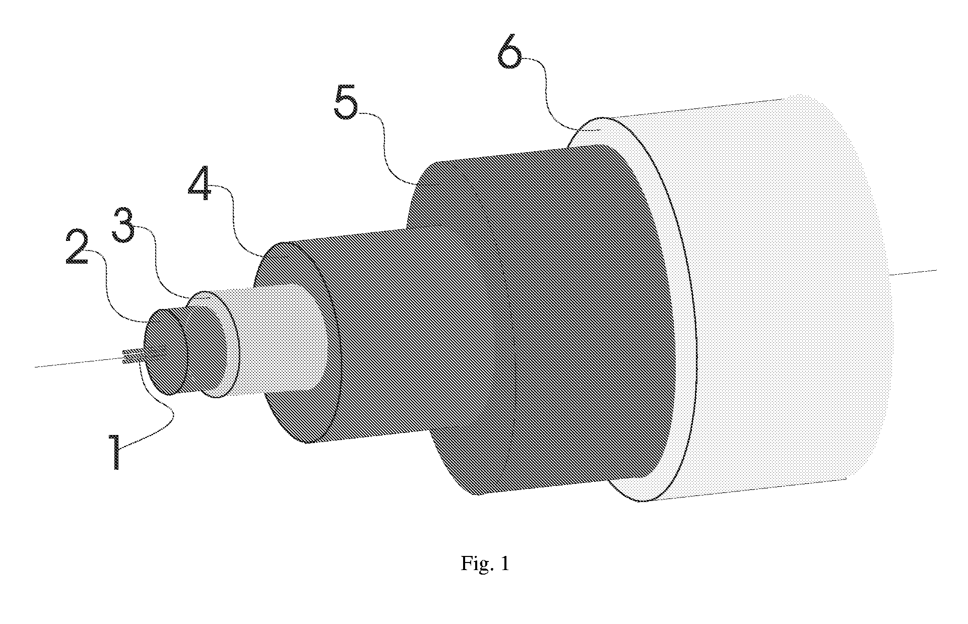
[0016]The battery technology used in this invention is based on thin film technology. The battery consists of an active (core) layer with a typical thickness in the range of 10-20 μm per cell (cell stacking is also possible), which is deposited on a foil or a filament. On top of the active layer a passivation layer with a thickness in the range of 5-80 μm is deposited. The battery fabricated by such technology is totally self-contained, i.e. without the need for further packaging. Due to the small thickness of the thin film battery incredible flexibility can be obtained. The battery is either fabricated in a strip geometry having dimensions of e.g. 5 mm width or on metal filaments or metal coated filaments. The processing is done on endless lanes or on short pieces of the foil or filament.
[0018]In this way a thin elongate and flexible thread like battery is achieved, which is easily stored at any convenient space by folding or winding into a desired shape. As the elongate conductive core also functions as carrier, no carrier layer is needed and this will allow more volume efficient batteries to be made. More than one sequence of the mentioned layers may be deposited on top of each other, thus allowing stacking of the battery as is well known in the art.

Problems solved by technology

With traditional rechargeable battery technology, it is not possible to obtain a solution which combines sufficient battery capacity and a generic battery size which fits into any hearing aid regardless of its shape and size.
This is primarily caused by the huge diversity of shapes and sizes of the hearing aids (especially ITE types) and by the lack of true flexibility of the batteries which are currently available.
So far it has proved very difficult to realise these functions in the very limited space inside a hearing aid.

Method used


Image

  • Hearing Aid with Rechargeable Battery and Rechargeable Battery
  • Hearing Aid with Rechargeable Battery and Rechargeable Battery
  • Hearing Aid with Rechargeable Battery and Rechargeable Battery

Examples


Embodiment Construction

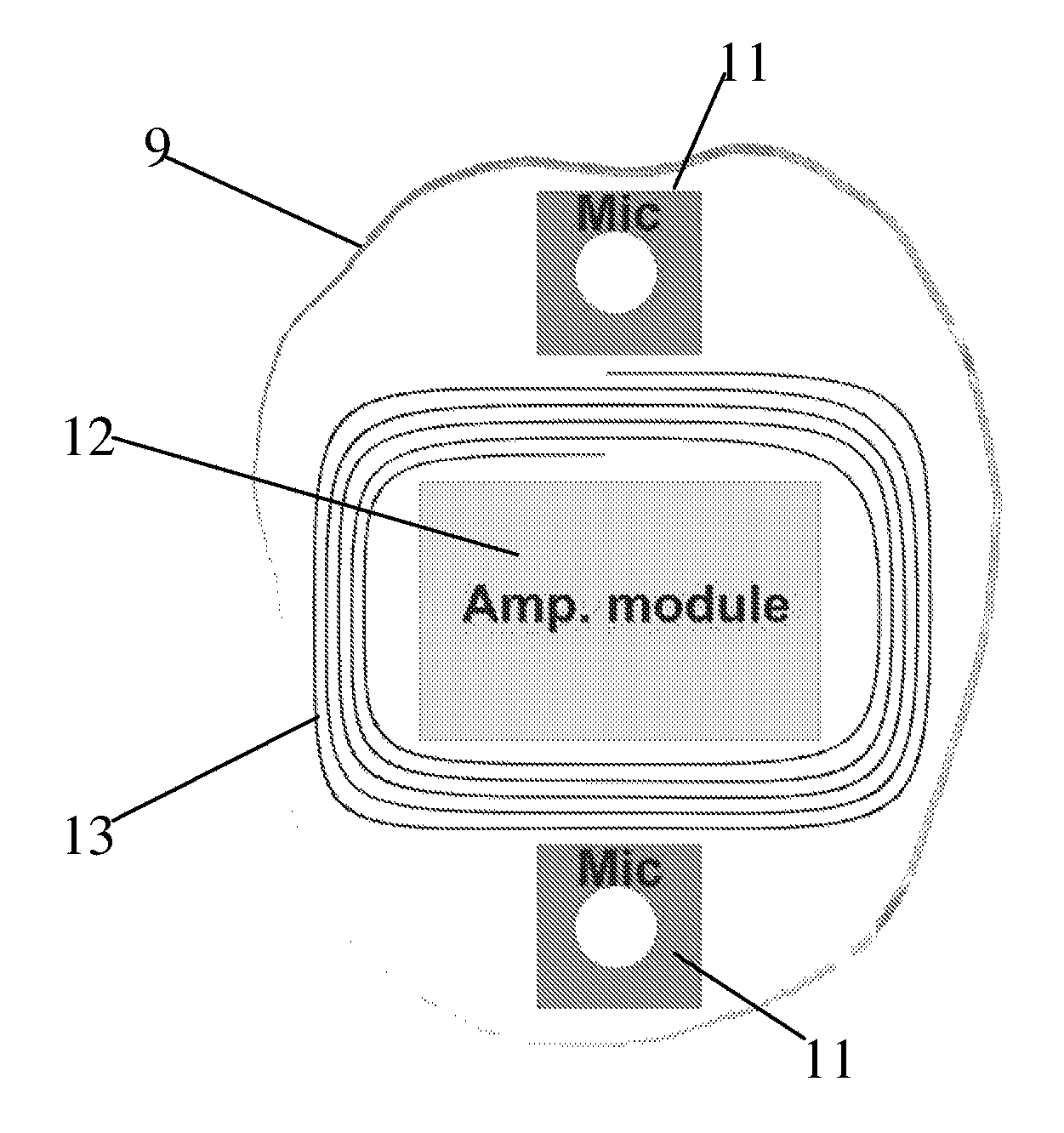
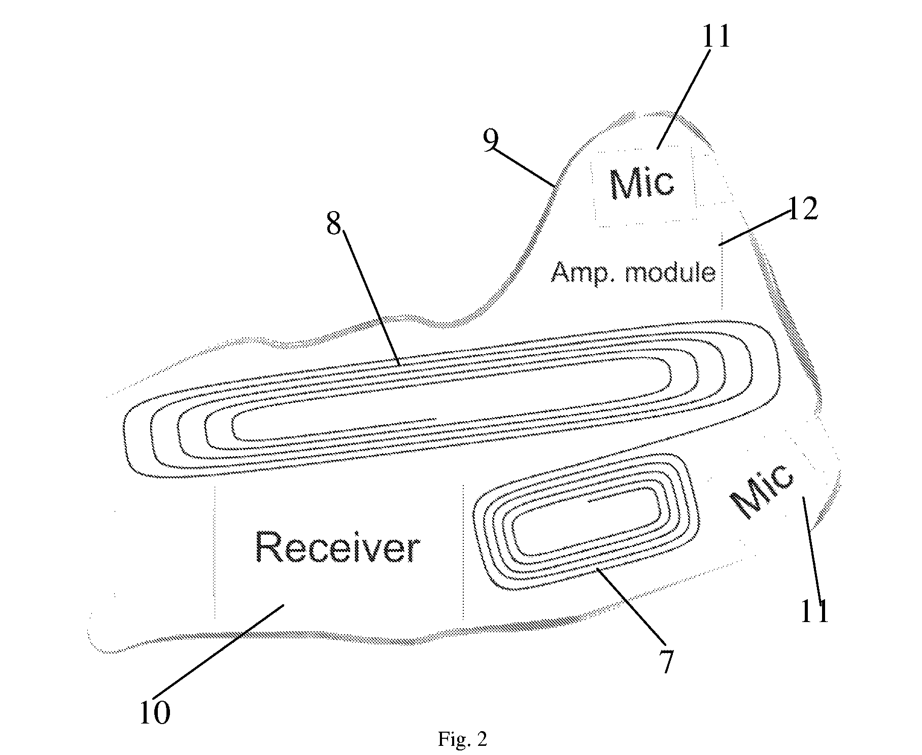
[0030]The battery in FIG. 1 comprises a core part 1. Preferably the core 1 comprises one or several filaments of a conducting material. In a preferred embodiment the filaments are made of metal material. Other possibilities are metal coated filaments of eg. glass, polymer or carbon. This part of the battery is either anode or cathode current collector. In the following it is assumed that the filaments 1 functions as the cathode current collector. In a layer surrounding the filaments the cathode material 2 is provided. On top of the cathode an electrolyte material 3 is provided. The electrolyte covers the entire outer radial surface of the cathode material 2, and on top of the electrolyte layer the anode material 4 is supplied. The anode current collector 5 is the last active part of the battery and is provided on the anode material 4. The current collector 5 could be a metal layer which is provided on top of the anode 4, or metal filaments could be woven onto the anode 4. Also a com...


PUM


Abstract

A rechargeable battery is provided comprising a flexible elongate electron conductive core (1) surrounded by a first electrochemically active layer (2), and a second electrochemically active layer (4), separated by a separation layer (3) and where an electron conducting element (5) contacts the outer surface of the second electrochemically active layer, whereby at least one of the two electrochemically active layers (2, 4) and the separation layer (3) are comprised of thin-film layers. Further a hearing aid is provided wherein a battery comprising thin film layers is provided. Such a battery may be curled or wound to accommodate an irregular space inside the hearing aid.

Description

BACKGROUND OF THE INVENTION[0001]In hearing aids the power supply is a critical factor and a very large portion of modern hearing aids is occupied by the battery. Decreasing the battery size then allows the overall size of the hearing aid to be decreased. Further, longer battery life is desired especially when it comes to rechargeable batteries. With traditional rechargeable battery technology, it is not possible to obtain a solution which combines sufficient battery capacity and a generic battery size which fits into any hearing aid regardless of its shape and size. This is primarily caused by the huge diversity of shapes and sizes of the hearing aids (especially ITE types) and by the lack of true flexibility of the batteries which are currently available. Further in modern hearing aids a number of wireless applications are requested. This is not only wireless recharge of the battery but also different wireless communication possibilities, such as telecoil, FM antenna and digitally...

Claims


Application Information

Patent Timeline
IPC IPC(8): H04R25/00H01M10/36H01M4/58H01M4/38H01M10/052H01M10/0562H01M10/0587
CPCH01M4/66H01M4/75H01M10/0431H01M10/052H01M10/0562Y02E60/122H01M10/46H01M2300/0071H02J7/025H04R25/00H04R2225/31H01M10/0587H02J7/0042Y02E60/10H02J50/005H02J50/10Y02P70/50H01M10/48H02J7/02
Inventor PETERSEN, ANDERS ERIKRASMUSSEN, FRANK ENGELPOULSEN, HENNING KNAKGUDNASON, GUNNAR
Owner OTICON
Learn More