
Sterilizer

a sterilizer and ultraviolet radiation technology, applied in the direction of material analysis using wave/particle radiation, disinfection, instruments, etc., can solve the problems of high failure rate of lamps and ballasts, degraded uv output, and high maintenance cost resulting from frequent lamp replacements. achieve the effect of facilitating energy saving and controlling flow pacing

Inactive Publication Date: 2008-06-05
SEVEN TRENT WATER PURIFICATION INC
View PDF10 Cites 24 Cited by
  • Summary
  • Abstract
  • Description
  • Claims
  • Application Information

AI Technical Summary

Benefits of technology

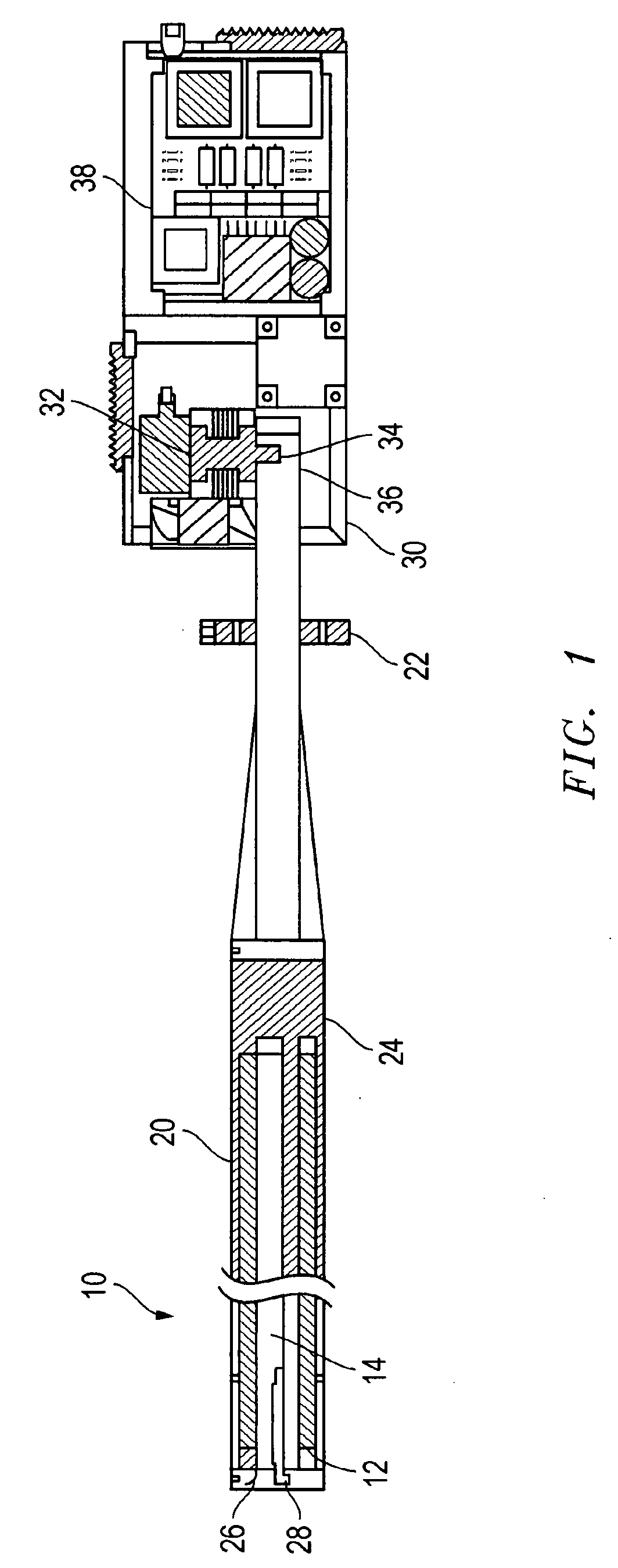
[0007]The waveguide of this invention is essentially UV transparent to allow UV light to pass through but effectively opaque to microwaves in order to substantially contain the microwaves within the waveguide. Containing the microwaves within the enclosure formed by the waveguide improves the disinfection qualities of the UV lamp assembly by emitting more UV rays to the surrounding fluids or solids. Because the waveguide is comprised of a conducting material, for example stainless steel, copper or brass, that blocks the path of the microwaves, the waveguide is able to substantially prevent microwaves from escaping thereby directing the bulk of the microwaves to the UV lamps for optimal UV output.
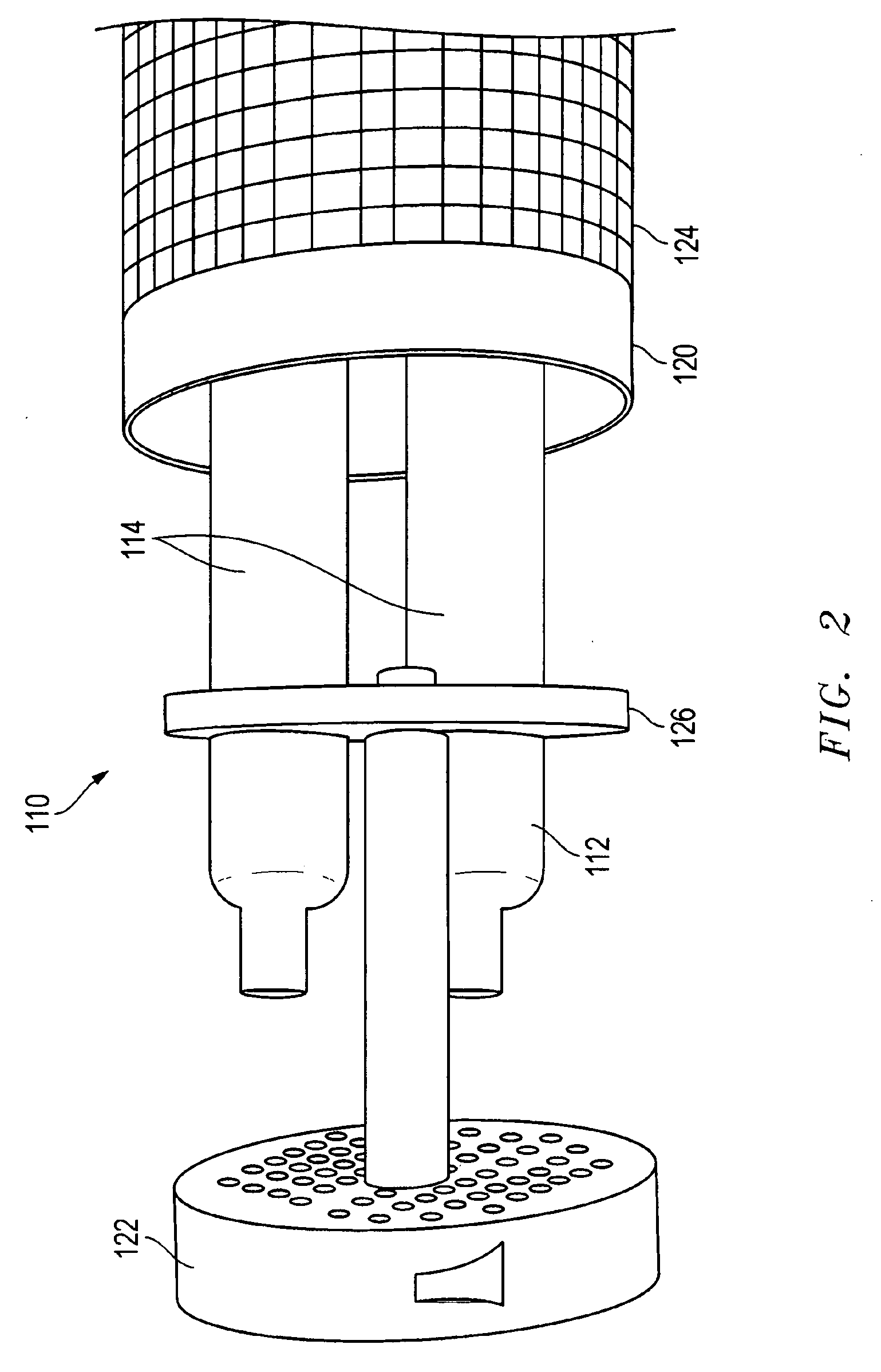
[0009]The quartz sleeve, however, prevents the ingress of fluids into the waveguide. In other embodiments, the lamp assemblies are grouped in multiples to form one or more lamp modules. Each lamp module can be switched on and off or, turned up or down, to match flow. The modular design is used to meet varying flow rates and disinfection demands. In yet a further embodiment, the lamp assembly comprises one or more lamp clusters. Preferably, the lamp clusters comprise one or more electrodeless ultraviolet (“UV”) lamps. The electrodeless UV lamps are excited by microwaves to emit UV rays. The UV lamps emit monochromatic or polychromatic UV radiation. The dominant wavelength of the UV radiation is from 240 nm to 310 nm.
[0010]Advantageously, the waveguide comprises a shape and size to wholly surround the lamp clusters so as to substantially contain the microwaves within the waveguide. The waveguide further comprises a flange. In another embodiment, the waveguide further comprises a mesh comprising intersecting metallic filaments and an end cap. The mesh extends from the flange to the end cap. The intersecting metallic filaments of the mesh define holes. The holes comprise a size smaller than the wavelength of the microwaves so as to avoid microwave leakage. The flange, end cap and mesh of the waveguide, form an enclosure. The waveguide enclosure contains the microwaves transmitted by the microwave generator while allowing the emission of UV rays from the waveguide. The waveguide can have a cylindrical or rectangular form.
[0011]Preferably, the end cap is distal to the flange. The end cap further comprises perforations wherein the perforations comprise a size smaller than the size of the microwave wavelengths to substantially reduce microwave leakage from the lamp assembly. The end cap also has mounting means for attaching the electrodeless UV lamps to the waveguide.
[0012]A housing encloses a microwave generator. The housing is coupled to the waveguide by a flange. The microwave generator generates and transmits microwaves that excite the UV lamps. In one embodiment, the microwave generator comprises a magnetron. The housing further comprises a power supply for the microwave generator. The housing is releasably connected to the flange of the waveguide so as to allow for easy and quick detachment of the housing from the waveguide. This facilitates removal of the microwave generator or power supply contained within the housing making the system more cost effective to maintain and repair.

Problems solved by technology

Another problem with traditional UV lamps is the high failure rate of the lamps and ballasts.
The maintenance costs resulting from frequent lamp replacements is substantial.
The UV output degrades over time.
Another problem with the existing UV systems is the lack of a mechanism to turn the systems on and off quickly.
Frequent switching of traditional electroded lamps wears them out very quickly.

Method used


Image

  • Sterilizer
  • Sterilizer
  • Sterilizer

Examples


Embodiment Construction

[0022]The lamp assembly and system of the present invention is used to treat water, waste water and air for both human consumption and industrial process. It also sterilizes solid items that may be contaminated. The process of purification or fluids or sterilization of items is achieved by exposure to UV radiation. A high frequency current in the form of microwaves is applied to electrodeless UV lamps. The lamp assembly is wholly surrounded by a waveguide that traps the microwaves within the waveguide enclosure. In this way, the microwaves travel the full length of the UV bulbs to stimulate the entire bulb to emit UV rays.

[0023]The microwaves collide with and ionize the gas atoms within the UV lamps to form a plasma by a process of impact ionization. As a result of avalanche ionization, the conductivity of the ionized gas rapidly rises, allowing higher currents to flow through the lamp. The mercury within the UV lamp is likewise ionized to emit light in the UV region of the spectrum...


PUM

PropertyMeasurementUnit
dominant wavelengthaaaaaaaaaa
wavelengthsaaaaaaaaaa

Abstract

A lamp assembly comprising one or more lamp clusters. Each lamp cluster comprises one or more electrodeless UV lamps which are excited by microwaves emitted from a microwave generator. The microwave generator and power supply are enclosed within a housing that is integral with the lamp clusters. The lamp clusters are wholly surrounded by a waveguide. The waveguide, comprising a flange and a distal end cap connected by a mesh, forms an enclosure. The waveguide is essentially UV transparent to allow UV light to pass through but effectively opaque to microwaves in order to substantially contain the microwaves within the waveguide enclosure.

Description

CROSS REFERENCES TO RELATED CASES[0001]This is a continuation in part of U.S. patent application Ser. No. 09 / 831,449, filed Aug. 13, 2001, abandoned contemporaneously with the filing of this application.FIELD OF INVENTION[0002]The present invention relates to disinfection systems using ultraviolet radiation, particularly disinfection systems having a UV lamp assembly.BACKGROUND OF THE INVENTION[0003]Ultraviolet (UV) radiation systems are used in the purification of water and the sanitization of a variety of items. The UV radiation and any ozone produced by the UV radiation act to kill bacteria and germs.[0004]Traditional water disinfection systems using mercury UV lamps generate radiation through gas discharge. A critical component in the operation of mercury UV lamps is the pressure of the mercury. A UV lamp is filled with a gas containing low pressure mercury vapour and argon or xenon. When the microwaves are turned on, electrons are emitted. These electrons collide with and ioniz...

Claims


Application Information

Patent Timeline
Patent Type & Authority Applications(United States)
IPC IPC(8): A61L2/10
CPCA61L2/10C02F1/32H01J65/044C02F2201/3224C02F2201/004Y10S422/905Y10S422/906Y10S422/907
Inventor LUCAS, JAMESMORRUZZI, JAMES
Owner SEVEN TRENT WATER PURIFICATION INC
Learn More