
Fin-pipe shaped radiator specially adapted to a semiconductor chilling unit and the method of making same

Inactive Publication Date: 2008-06-05
GUO CHEN
View PDF13 Cites 8 Cited by
  • Summary
  • Abstract
  • Description
  • Claims
  • Application Information

AI Technical Summary

Benefits of technology

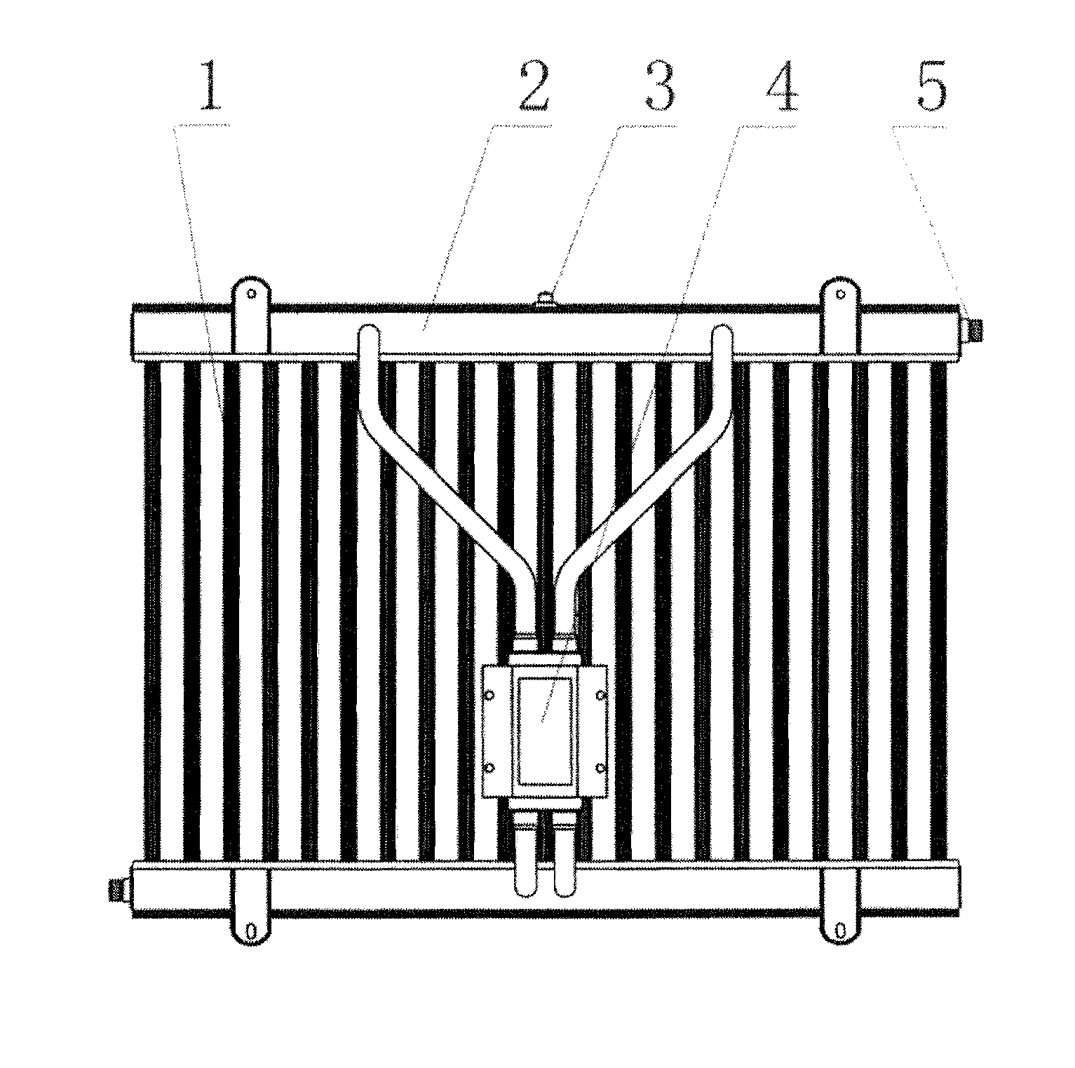
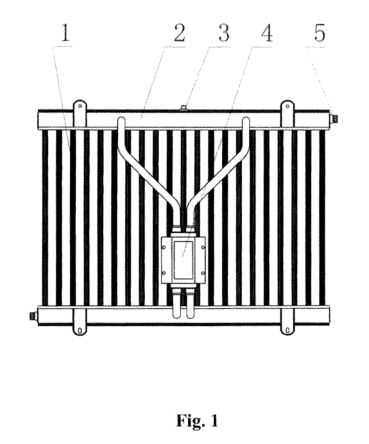
[0039]This invention intends to introduce a fin-pipe shaped radiator specially applied to semiconductor chilling unit with favorable heat radiating effect and simplified structure which is suitable for standardized production.
[0055]1. The horizontal pipe and vertical pipe are shaped by a one-off extruding, the cover panel and through-hole are blanked by a one-off punching, and assembly is finished by a one-off welding in a soldering furnace. The main body of the radiator is shaped into a vertical-pipe radiator which has overcome the disadvantages in coil-pipe type radiator of simplex circulation line and too many detours that block circulating and in plate type radiator of low resistance to pressure that will make the radiator distort or deform or make the weld points crack and so on.
[0058]4. Bar fins are added to the surface of the vertical pipe and horizontal pipe to enlarge the effective heat radiating area and decrease the number of welding points.

Problems solved by technology

Furthermore, this kind of radiator has numerous welding points on the surface of the heat radiating pipes and is manufactured by complicated welding techniques which can be only realized by manual welding, thus it is not suitable for industrialized batch production, the parts are difficult to be manufactured by standardized production, and the reliability of welding quality is very weak.

Method used


Image

  • Fin-pipe shaped radiator specially adapted to a semiconductor chilling unit and the method of making same
  • Fin-pipe shaped radiator specially adapted to a semiconductor chilling unit and the method of making same
  • Fin-pipe shaped radiator specially adapted to a semiconductor chilling unit and the method of making same

Examples


Embodiment Construction

[0039]This invention intends to introduce a fin-pipe shaped radiator specially applied to semiconductor chilling unit with favorable heat radiating effect and simplified structure which is suitable for standardized production.

[0040]The other is to introduce a fin-pipe shaped radiator specially applied to semiconductor chilling unit with favorable heat radiating effect which is suitable for industrialized production.

[0041]The technical solution for this invention is generally as follows:

[0042]A. Separately manufacture shaped vertical pipe (1), horizontal pipe and arched plate (2) by extruding technique, and manufacture end caps (7) (with groove welded around) and cover panel (9) (with hole flanging on the surface and grooves at both sides) by extruding technique with plate material coated with welding dressing; or machine through-hole directly on the surface of the horizontal pipe;

[0043]B. Cut arched plate (2) and vertical pipe (1) into corresponded length;

[0044]C. Assemble arched pl...


PUM

PropertyMeasurementUnit
Angleaaaaaaaaaa
Transparencyaaaaaaaaaa

Abstract

This invention relates to a radiator and its preparation method, and especially refers to a fin-pipe shaped radiator specially applied to semiconductor chilling unit and its preparation method. This radiator consists of vertical pipe and upper & lower horizontal pipe (both ends are blocked) welded into the heat radiation chamber, and the evaporator connected through pipeline with axially extending fins distributed on the external surface of the horizontal pipe and the vertical pipe in an angle “α” at the joint within the range of 0°<α≦90°. The main components are manufactured into sections by extruding, punching or other machining techniques and then soldered into a radiator. It has overcome the disadvantages of various and numerous welding points, complicated techniques and so on in existing manufactures, and has realized an industrialized batch production upon simple and reliable techniques.

Description

TECHNICAL FIELD [0001]This invention relates to a radiator and its preparation method, and especially refers to a fin-pipe shaped radiator specially applied to semiconductor chilling unit and its preparation method.BACKGROUND OF THE INVENTION [0002]So far in disclosed literatures, the overall structure of vertical pipe radiator are assembled by manual welding through perforating the upper & lower horizontal pipe and vertical pipe as well as adding heat radiating filaments. The horizontal pipe are usually formed by bare pipes welded to the vertical pipe, and the heat radiating areas on original horizontal pipe and vertical pipe are realized by welding filament and fins to the bare pipes, therefore the connecting of the heat radiating filaments and fins to the bare pipes can only be realized by spot welding which will restrict the heat radiating areas, and as a result, the heat transfer efficiency is only 20%˜30% of that in the overall structure. Furthermore, this kind of radiator has...

Claims


Application Information

Patent Timeline
IPC IPC(8): B21D53/06F28D15/00
CPCB23P15/26B23P2700/09F28D15/0266F28D2021/0031F28F3/048F28F9/0224Y10T29/49359F28F2009/0292F28F2255/16F28F2265/12H01L2924/0002H01L23/427H01L2924/00
Inventor WANG, SHUANGLING
Owner GUO CHEN
Learn More