Eureka AIR delivers breakthrough ideas for toughest innovation challenges, trusted by R&D personnel around the world.

Wireless Power Supply System and Wireless Power Supply Method

a power supply system and wireless technology, applied in the direction of loop antennas, electric devices, batteries for several simultaneous use, etc., can solve the problem that an unspecified number of users can gain electric energy, and achieve the effect of increasing convenience for users

Active Publication Date: 2008-05-29
SEMICON ENERGY LAB CO LTD
View PDF19 Cites 353 Cited by
  • Summary
  • Abstract
  • Description
  • Claims
  • Application Information

AI Technical Summary

Benefits of technology

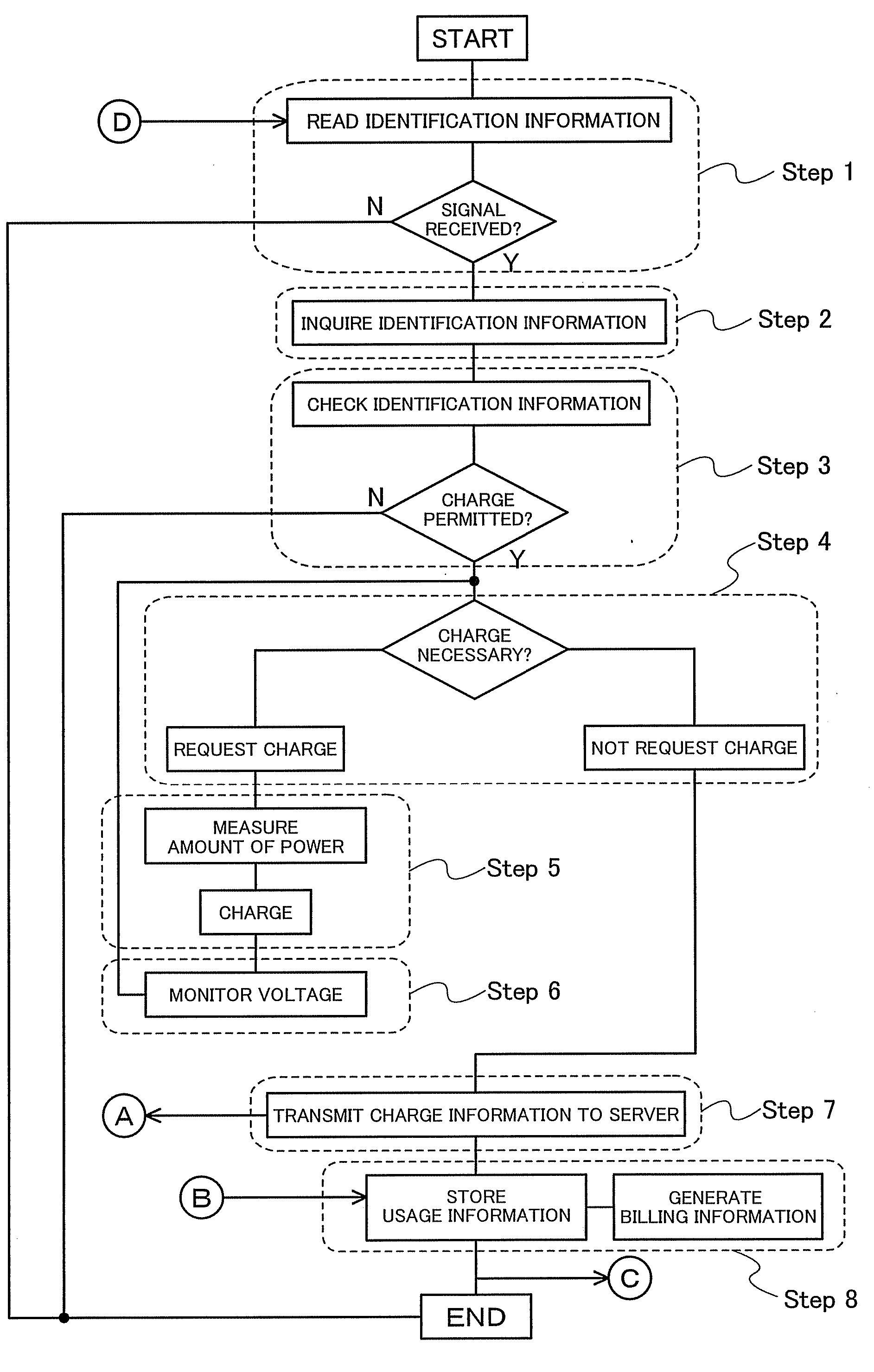
[0007]Thus, it is an object of the present invention to provide a system for improving convenience for users, by which a portable electronic device or the like can be charged even in a place where utility power is not available. It is another object to provide a system which allows a service provider to easily perform customer management.
[0013]According to the present invention, a user can be identified, and a power storage device of the user can be charged. In this case, since an identification number is stored in the power storage device and registered with the management server in advance, a user does not need to perform any troublesome operation in charging. In addition, convenience for users can be increased because charging can be performed without contact and thus there is no need to carry around a heavy AC adaptor or secondary battery. On the other hand, a provider can offer a service to specific customers so that the provider can meet customers' needs and can unify management of customer information such as billing.

Problems solved by technology

However, a conventional portable charging device has a problem in that an unspecified number of users can gain electric energy which is supplied from an external device if they have a means to receive the electric energy.

Method used


Image

  • Wireless Power Supply System and Wireless Power Supply Method
  • Wireless Power Supply System and Wireless Power Supply Method
  • Wireless Power Supply System and Wireless Power Supply Method

Examples


embodiment mode 1

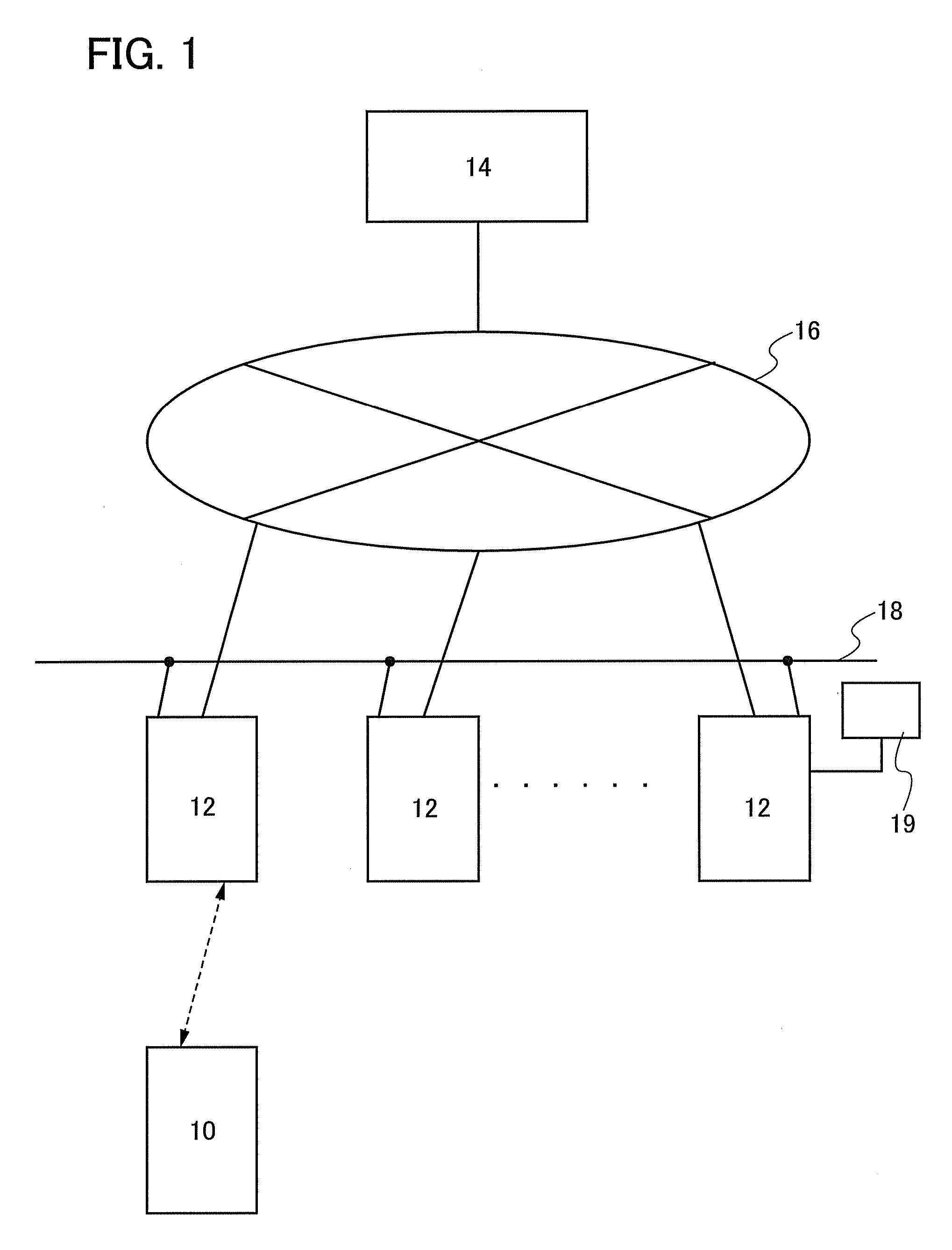
[0033]This embodiment mode describes a wireless power supply system with reference to FIG. 1. This wireless power supply system has a power storage device 10 and a terminal charging device 12 as components. The terminal charging device 12 may be connected to a management server 14. The power storage device 10 functions to store electric power and is charged by receiving electric waves which are supplied from the terminal charging device 12. The power storage device 10 can be carried around by a user. The power storage device 10 is present in a living space in a distributed manner by being carried around arbitrarily by a user. The power storage device 10 can be charged while within a range where it can receive electric waves which are transmitted from the terminal charging device 12.

[0034]One or more terminal charging devices 12 are prepared. The installation site of the terminal charging device 12 may be determined in consideration of convenience for a user of the power storage devi...

embodiment mode 2

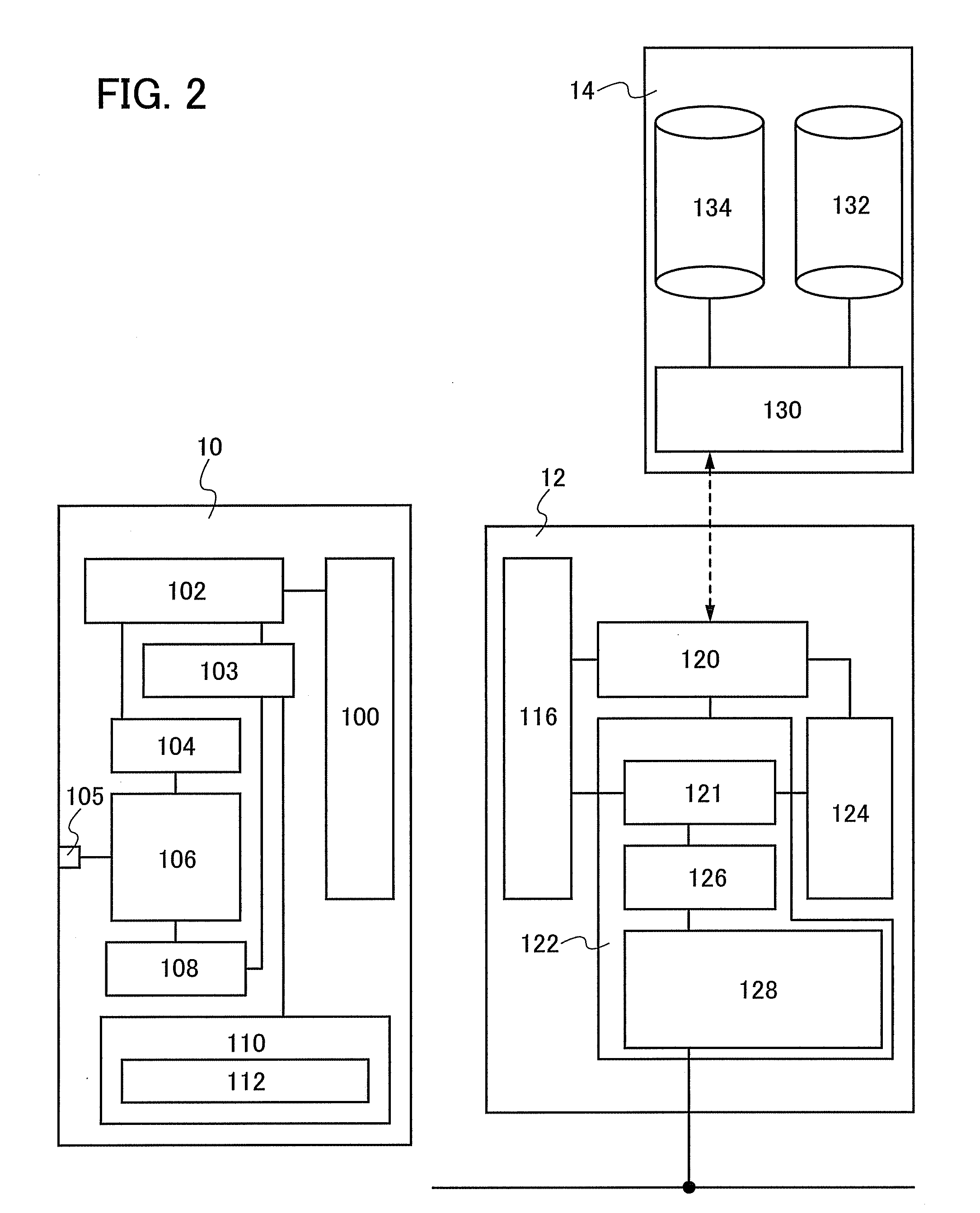
[0038]The wireless power supply system of the present invention includes a power storage device which can be charged without contact, a terminal device which supplies electric power to the power storage device, and a management server which manages electric power that is supplied to the power storage device. FIG. 2 shows one structural example of the wireless power supply system.

[0039]The power storage device 10 has a power storage portion 106 which stores electric power. The power storage portion 106 stores electric power obtained by rectification by a charging portion 104 of electric waves received by an antenna 100. The power storage portion 106 is preferably formed using a capacitor such as an electric double layer capacitor or a ceramic capacitor. Because a capacitor can store electric power without chemical reaction, unlike a lead battery or a lithium-ion battery (secondary battery), it has advantages of a short charging time and no deterioration due to repetitive charging and...

embodiment mode 3

[0081]A structure for notifying a user of a power storage device of usage information in Embodiment Mode 1 is described. Note that similar components to those in Embodiment Mode 1 are denoted by the same reference numerals, and description of the components is omitted unless particularly needed.

[0082]FIG. 6 shows a structural example of a wireless power supply system according to this embodiment mode. A main change from FIG. 2 is that the power storage device 10 is provided with a display portion 115. In addition, the memory portion 110 is provided with a usage information storage portion 114 so that a user can see usage information.

[0083]The display portion 115 of the power storage device 10 can be a liquid crystal panel, an electrochromic panel, an electroluminescent panel, a display panel using a contrast medium such as electronic ink, or the like. Note that the contrast medium refers to a medium in which an electrophoretic dispersed liquid is encapsulate in a microcapsule and wh...


PUM

PropertyMeasurementUnit
thicknessaaaaaaaaaa
thicknessaaaaaaaaaa
thicknessaaaaaaaaaa

Abstract

An object is to provide a system for improving convenience for users, by which a portable electronic device or the like can be charged even in a place where utility power is not available. Another object is to provide a system which allows a service provider to easily perform customer management. A wireless power supply system includes a power storage device having a power storage portion, a terminal charging device for wirelessly supplying electric power to the power storage device, and a management server having user information. Electric power can be supplied to specified users by intercommunication of user information between the power storage device and the terminal charging device and between the terminal charging device and the management server.

Description

BACKGROUND OF THE INVENTION[0001]1. Field of the Invention[0002]The present invention relates to a system for charging a power storage device. The present invention specifically relates to a wireless power supply system and a wireless power supply method for charging a power storage device using electric waves.[0003]2. Description of the Related Art[0004]At various scenes of social life, the processing of information through a computer network is performed, and the realization of a ubiquitous society where convenience of the processing of information through a computer network can be enjoyed is approaching. The word “ubiquitous” comes from the Latin meaning “existing or being everywhere” (being omnipresent) and is used in a sense that the processing of information using computers is naturally widespread throughout a living environment without any awareness of computers at anytime or anywhere.[0005]A portable electronic device such as a cellular phone requires a battery charger for c...

Claims


Application Information

Patent Timeline
Patent Type & Authority Applications(United States)
IPC IPC(8): H02J17/00G06F17/40G06Q30/00H01M10/44H02J7/00H02J50/00H02J50/10H02J50/20H02J50/70
CPCG06Q50/06H01Q1/243H01Q7/00H02J2007/0098H02J7/00H02J17/00H01Q21/30H02J50/10H02J50/20H01M10/4257Y02E60/10H02J50/70H02J50/40H02J50/80H02J50/005H02J7/0013H02J7/00034
Inventor ARAI, YASUYUKI
Owner SEMICON ENERGY LAB CO LTD
Why Eureka
Eureka Blog
Learn More