
Method of forming sensor for detecting gases and biochemical materials, integrated circuit having the sensor, and method of manufacturing the integrated circuit

a biochemical material and sensor technology, applied in the field of forming sensors, can solve the problems of difficult integration of sensors and unit elements, difficult miniaturization process, etc., and achieve the effect of preventing the degradation of the integrated circuit caused by heating the unit devices when forming the sensors

Inactive Publication Date: 2008-05-29
ELECTRONICS & TELECOMM RES INST
View PDF13 Cites 171 Cited by
  • Summary
  • Abstract
  • Description
  • Claims
  • Application Information

AI Technical Summary

Benefits of technology

[0011]The present invention also provides a method of manufacturing an integrated circuit including a miniature sensor for detecting gases and biochemical materials and unit elements having various composite functions by low temperature processing without degrading or lowering characteristics of MOSFET-based unit elements.
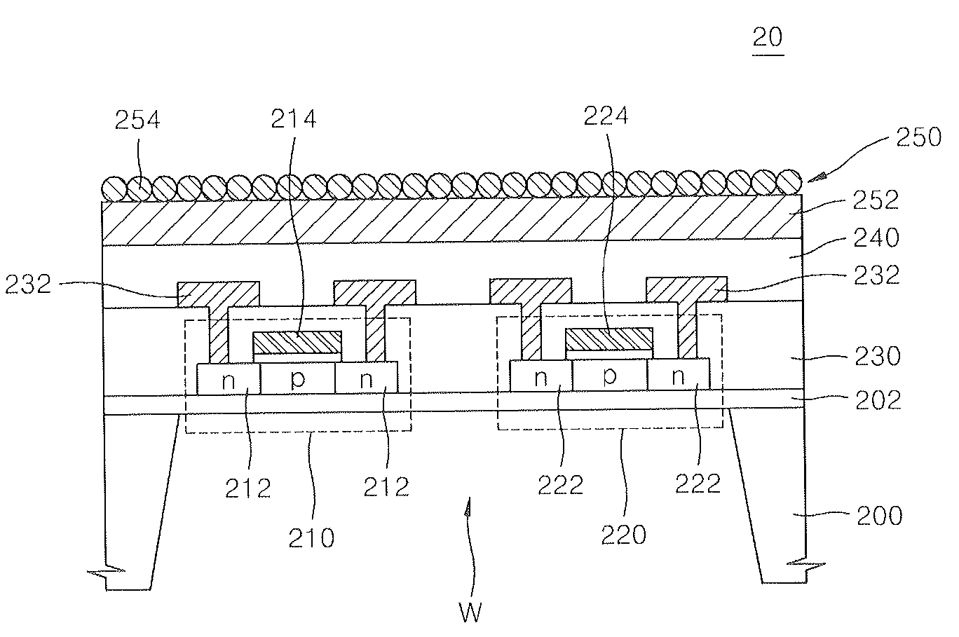
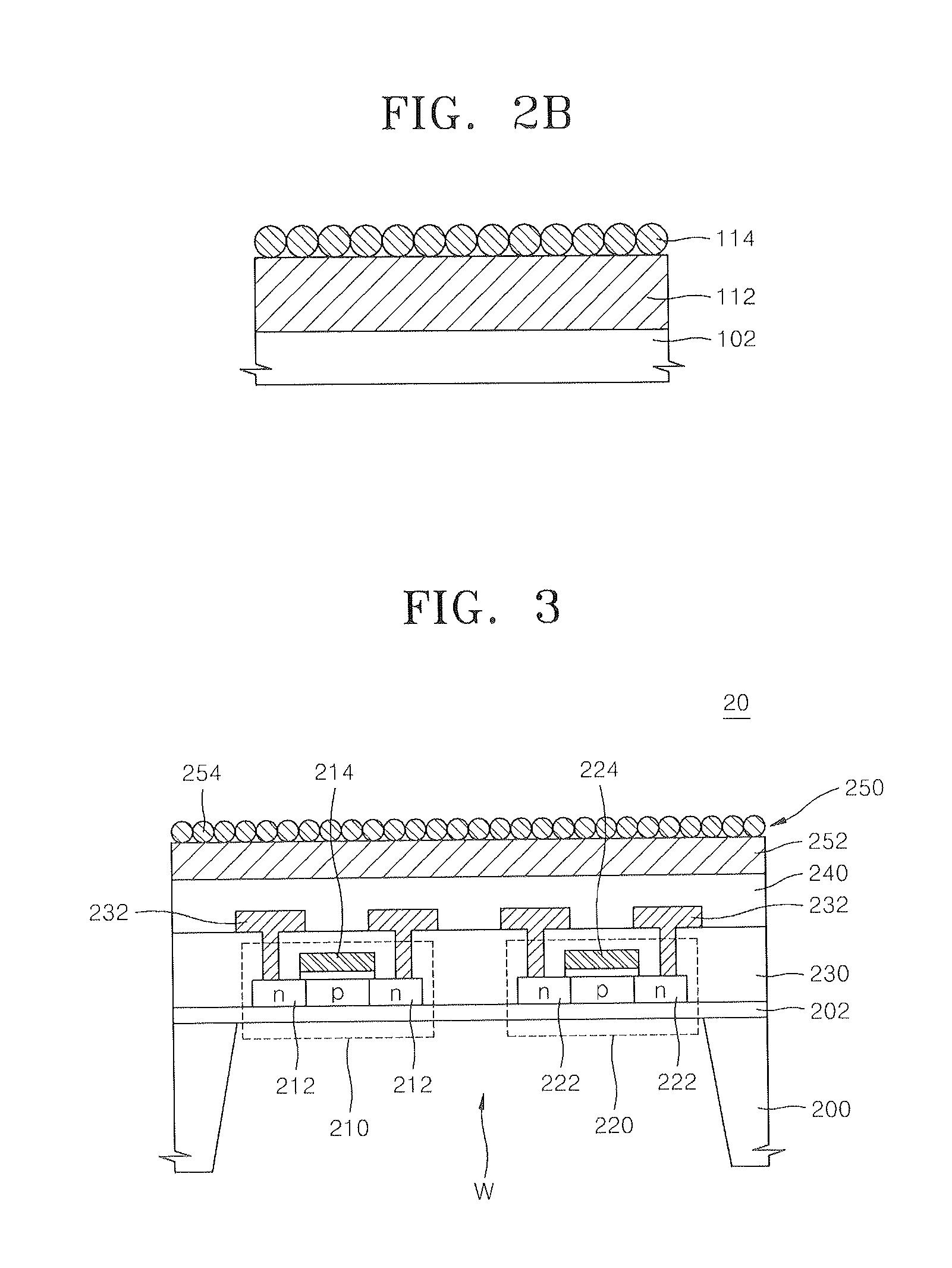
[0021]According to the present invention, a sensor for detecting gases and biochemical materials that can be formed without performing an additional thermal treatment at high temperature is embodied on a substrate where MOSFET unit devices are formed. Therefore, characteristics degradation of an integrated circuit caused by heating the unit devices when forming the sensor can be prevented, and fine unit elements having various composite functions can be integrated on a single substrate together with the sensor.

Problems solved by technology

However, currently-suggested sensors for detecting gases or biochemical materials are of a ceramic type or a thick film type, which, thus, make a miniaturization process difficult.
Accordingly, the integration of the sensors and the unit elements altogether is difficult.

Method used


Image

  • Method of forming sensor for detecting gases and biochemical materials, integrated circuit having the sensor, and method of manufacturing the integrated circuit
  • Method of forming sensor for detecting gases and biochemical materials, integrated circuit having the sensor, and method of manufacturing the integrated circuit
  • Method of forming sensor for detecting gases and biochemical materials, integrated circuit having the sensor, and method of manufacturing the integrated circuit

Examples


example 1

[0058]In order to make a metal oxide nano structure layer grow using sputtering facility, an electrode formed of a polycrystalline metal film having a thickness of about 1000 nm was formed on an upper surface of a silicon substrate in a plane orientation (100). Thereafter, the silicon substrate formed with the electrode was loaded in a reaction chamber having a ZnO target, and ZnO was grown by using RF sputtering. A pressure within the reaction chamber was controlled to roughly 3.8×10⁻³ Pa or less, before growing the ZnO nano structure, i.e., before loading the silicon substrate within the reaction chamber. When the ZnO nano structure was being grown within the reaction chamber, a pressure of about 2.3 Pa was maintained within the reaction chamber and an RF power of about 150 watt is applied. While the ZnO nano structure was being grown within the reaction chamber, a temperature within the reaction chamber was maintained at room temperature.

example 2

[0059]In order to observe the change of the nano structure form resulting from a quantity of oxygen in an ambient environment within the reaction chamber when making the metal oxide nano structure layer grow according to the method of the Example 1, ZnO nano structure was grown under a condition that O2 and Ar have a flow rate ratio (O2 / Ar) of 0, 0.2 and 0.4, respectively.

[0060]For this operation, after a Ti thin film was formed on a p-type (100) silicon substrate, a Cu film was formed thereon for about 5 minutes by electro-plating. Thereafter, ZnO was grown on a surface of the Cu film for 15 minutes within the sputtering reaction chamber maintaining the temperature and pressure of the ambient environment as described in Example 1.

[0061]FIG. 4 shows SEM images displaying results of growing the ZnO nano structure each obtained according to a flow rate ratio of O2 / Ar as a result of Example 2.

[0062]FIG. 5 illustrates results of analyzing X-ray diffraction peaks with respect to the resu...

example 3

[0069]In order to observe the change of the nano structure form associated with a growth within the reaction chamber when making the metal oxide nano structure layer grow by the method according to Example 1, two growth cases for 15 minutes and 50 minutes of the ZnO nano structure were compared under the state where the flow rate ratio (O2 / Ar) of O2 and Ar maintains 0.2 within the reaction chamber.

[0070]For this operation, samples having electrodes by sequentially forming Ti and Cu thin films on a p-type (100) silicon substrate were prepared by the method according to Example 2. Then, the samples were classified into two groups, and ZnO is grown for 15 minutes and 50 minutes on the electrodes with respect to the two groups in a sputtering reaction chamber wherein the temperature and the pressure were maintained in the ambient environment as described in Example 1.

[0071]FIG. 7 shows SEM images each displaying resultant structures where the ZnO nano structures are grown as the result ...


PUM


Abstract

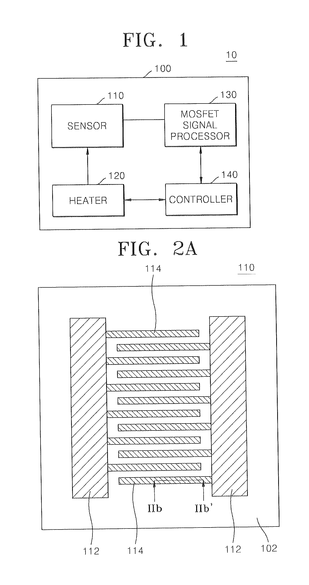
A method of forming a sensor for detecting gases and biochemical materials that can be fabricated at a temperature in a range from room temperature to 400° C., a metal oxide semiconductor field effect transistor (MOSFET)-based integrated circuit including the sensor, and a method of manufacturing the integrated circuit are provided. The integrated circuit includes a semiconductor substrate. The sensor for detecting gases and biochemical materials includes a pair of electrodes formed on a first region of the semiconductor substrate, and a metal oxide nano structure layer formed on surfaces of the pair electrodes. A heater is formed to perform thermal treatment to re-use the material detected in the metal oxide nano structure layer. Also, a signal processor is formed by a MOSFET to process a predetermined signal obtained from a quantity change of a current flowing through the pair of electrodes of the sensor. To form the sensor, the metal oxide nano structure layer is formed on surfaces of the pair of electrodes at a temperature in a range from room temperature to 400° C.

Description

CROSS-REFERENCE TO RELATED PATENT APPLICATION[0001]This application claims the benefit of Korean Patent Application No. 10-2006-0083570, filed on Aug. 31, 2006, in the Korean Intellectual Property Office, the disclosure of which is incorporated herein in its entirety by reference.BACKGROUND OF THE INVENTION[0002]1. Field of the Invention[0003]The present invention relates to a method of forming a sensor, an integrated circuit having the sensor, and a method of manufacturing the integrated circuit. More particularly, the present invention relates to a method of forming a sensor for detecting gases and biochemical materials, an integrated circuit including a metal oxide semiconductor field effect transistor (MOSFET) having the sensor, and a method of manufacturing the integrated circuit.[0004]2. Description of the Related Art[0005]As environmental pollution and global warming have become more severe, the development of gas sensors for detecting the existence or quantity of a specific ...

Claims


Application Information

Patent Timeline
IPC IPC(8): H01L29/78H01L21/00
CPCG01N27/127G01N27/122B82Y15/00G01N27/12
Inventor YOUN, DOO HYEBMAENG, SUNGLYULKIM, SANG HYEOBPARK, JONGHYURKKANG, KWANG YONGLEE, SANG HOONJU, CHULL WON
Owner ELECTRONICS & TELECOMM RES INST
Learn More