Manufacturing Method of Semiconductor Device and Laser Processing Apparatus
a manufacturing method and laser processing technology, applied in manufacturing tools, welding/soldering/cutting articles, instruments, etc., can solve the problems of increased cost and decreased throughput, and achieve the effect of reducing manufacturing cost, simplifying lithography steps in forming openings, and reducing the number of lithography steps
- Summary
- Abstract
- Description
- Claims
- Application Information
AI Technical Summary
Benefits of technology
Problems solved by technology
Method used
Image
Examples
embodiment mode 1
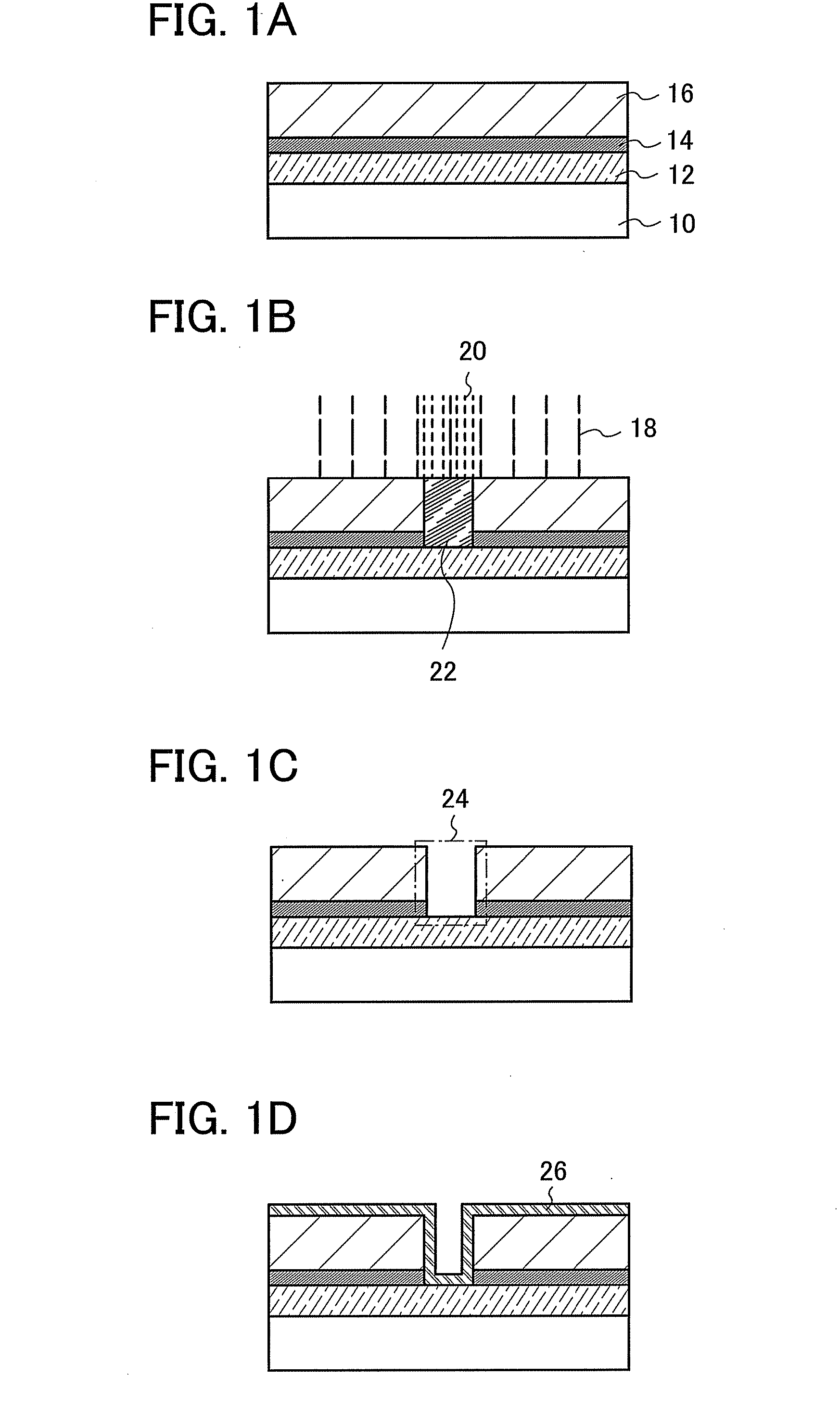
[0069] The present invention has a feature in that an opening is formed in a desired region without using a lithography technique with a photoresist. In this embodiment mode, an opening for electrically connecting conductive layers to each other is formed in an insulating layer. Hereinafter, one mode of a method for forming an opening in an insulating layer by applying the present invention will be specifically described with reference to FIGS. 1A to 1D.
[0070] First, a substrate 10 over which a conductive layer 12, a light absorbing layer 14, and an insulating layer 16 are sequentially stacked is prepared (see FIG. 1A). The substrate over which the conductive layer 12, the light absorbing layer 14, and the insulating layer 16 are sequentially stacked are an irradiated object of this embodiment mode.
[0071] As the substrate 10, a glass substrate, a quartz substrate, a sapphire substrate, a ceramic substrate, a semiconductor substrate, or the like is used. Note that a base insulating...
embodiment mode 2
[0095] In this embodiment mode, one structural example of a laser processing apparatus of the present invention will be described.
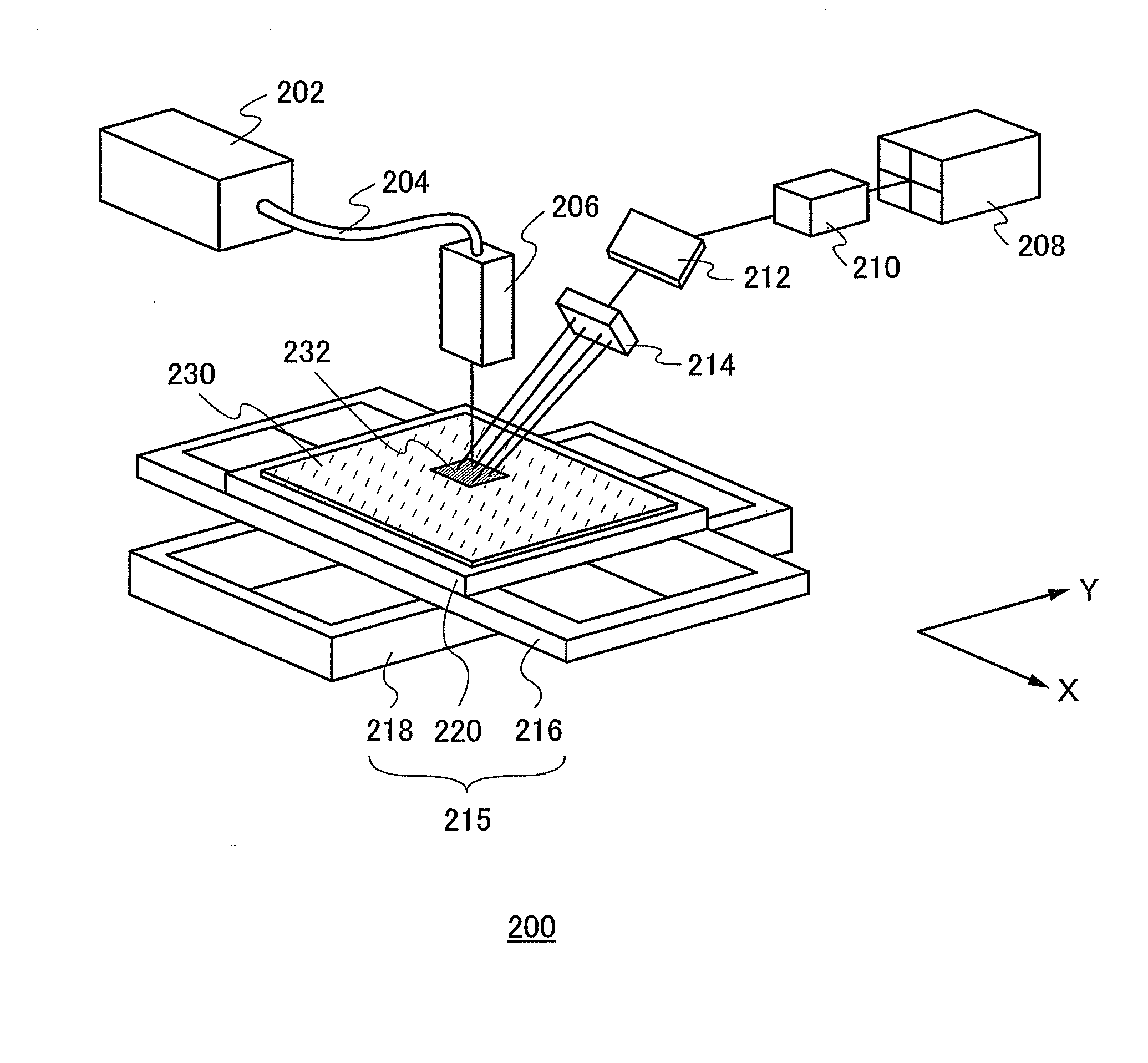
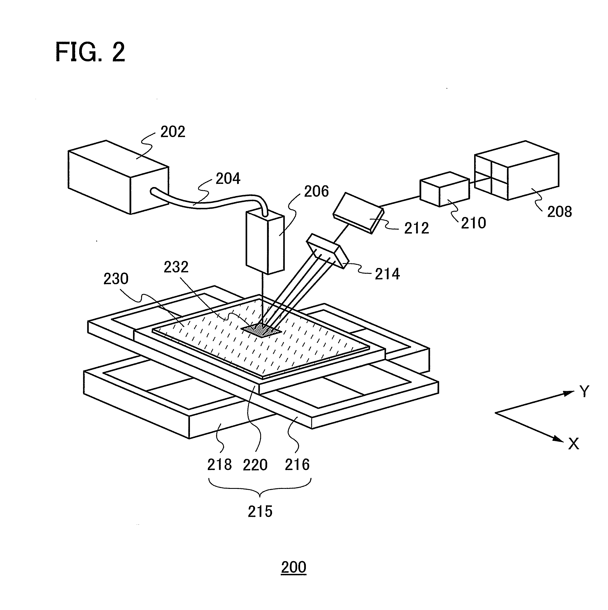
[0096] A schematic view of a laser processing apparatus is illustrated in FIG. 2. In FIG. 2, a laser processing apparatus 200 includes a first laser oscillation device 202, a first optical system 206 which shapes a laser beam, a second laser oscillation device 208, a second optical system 210 which shapes a laser beam, a diffractive optical element 214 which divides a laser beam passed through the second optical system 210 into a plurality of laser beams, and a stage 215.
[0097] The first laser oscillation device 202 includes a laser oscillator with which a multi-mode laser beam can be obtained. For example, an excimer laser oscillator of KrF, ArF, XeCl, or the like; a gas laser oscillator of He, He—Cd, Ar, He—Ne, or the like; a solid-state laser oscillator using a medium of a single crystal such as YAG, YVO4, forsterite (Mg2SiO4), YAlO3, or GdVO4 or a p...
embodiment mode 3
[0123] In this embodiment mode, a structural example of a laser processing apparatus different from that in Embodiment Mode 2 will be described.
[0124] A schematic view of a laser processing apparatus is illustrated in FIG. 4. In FIG. 4, a laser processing apparatus 300 includes a first laser oscillation device 302, a first optical system 306 which shapes a laser beam, a second laser oscillation device 308, a second optical system 310 which divides a laser beam into a plurality of laser beams, a first deflector 312 and a second deflector 314 which control traveling directions of laser beams, and a stage315.
[0125] The first laser oscillation device 302 includes a laser oscillator with which a multi-mode laser beam can be obtained. As the first laser oscillation device 302, specifically, a laser oscillator similar to the first laser oscillation device 202 shown in Embodiment Mode 2 can be used. When an oscillator of a YAG laser, a YVO4 laser, or an excimer laser is used for the first...
PUM
| Property | Measurement | Unit |
|---|---|---|
| diameter | aaaaa | aaaaa |
| thickness | aaaaa | aaaaa |
| thickness | aaaaa | aaaaa |
Abstract
Description
Claims
Application Information
 - R&D
- Intellectual Property
- Life Sciences
- Materials
- Tech Scout
- Unparalleled Data Quality
- Higher Quality Content
- 60% Fewer Hallucinations
Browse by: Latest US Patents, China's latest patents, Technical Efficacy Thesaurus, Application Domain, Technology Topic, Popular Technical Reports.
© 2025 PatSnap. All rights reserved.Legal|Privacy policy|Modern Slavery Act Transparency Statement|Sitemap|About US| Contact US: help@patsnap.com


