
Controlled pulse operations in non-volatile memory

Inactive Publication Date: 2008-01-31
SANDISK TECH LLC
View PDF86 Cites 54 Cited by
  • Summary
  • Abstract
  • Description
  • Claims
  • Application Information

AI Technical Summary

Benefits of technology

[0030]A passive element memory device is provided that includes memory cells comprised of a state change element in series with a steering element. Controlled pulse operations are used to perform resistance changes associated with set and reset operations in an array of memory cells. Selected memory cells in an array are switched to a target resistance state in one embodiment by applying a positive voltage pulse to selected first array lines while applying a negative voltage pulse to selected second array lines. An amplitude of voltage pulses can be increased while being applied to efficiently and safely switch the resistance of cells having different operating characteristics. The cells are subjected to reverse biases in embodiments to lower leakage currents and increase bandwidth. The amplitude and duration of voltage pulses are controlled, along with the current applied to selected memory cells in some embodiments. These controlled pulse-based operations can be used to set memory cells to a lower resistance state or reset memory cells to a higher resistance state in various embodiments.
[0031]A reverse bias can be applied to a memory cell to switch it from a first resistance state to a second resistance state in one embodiment. The amount of reverse bias can be increased for a selected set of memory cells to account for variances in the erase behavior of particular memory cells. One or more gradually increasing voltage pulses can be applied to selected word lines and / or bit lines to allow different cells to reset at various levels of applied reverse bias. Damage to cells that reset earlier is avoided while providing sufficient bias for harder to reset cells. Retry pulses can be incorporated in one or more embodiments but are not required.

Problems solved by technology

High bias conditions applied to program these cells can restrict the endurance of the steering element.
High leakage currents, program disturbances, read disturbances, etc. can pose difficulties when attempting to produce a memory device comprising one or more arrays of passive element memory cells that can be reliably fabricated, programmed, and read.
Moreover, slight differences between individual memory cells can pose difficulty when attempting to program multiple cells individually or concurrently.

Method used


Image

  • Controlled pulse operations in non-volatile memory
  • Controlled pulse operations in non-volatile memory
  • Controlled pulse operations in non-volatile memory

Examples


Embodiment Construction

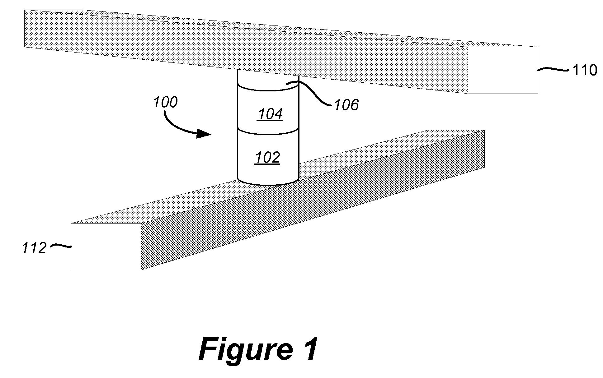
[0050]FIG. 1 depicts an exemplary structure for a non-volatile memory cell that can be used in accordance with embodiments of the present disclosure. A two-terminal memory cell 100 as depicted in FIG. 1 includes a first terminal portion connected to a first conductor 110 and a second terminal portion connected to a second conductor 112. The memory cell includes a steering element 102 in series with a state change element 104 and an anti-fuse 106 to provide non-volatile date storage. The steering element can take the form of any suitable device exhibiting a nonlinear conduction current characteristic such as a simple diode. The state change element will vary by embodiment and can include numerous types of materials to store data through representative physical states. State change element 104 can include resistance change materials, phase change resistive materials, etc. For example, a semiconductor or other material having at least two levels of detectable resistance change (e.g., l...


PUM


Abstract

A passive element memory device is provided that includes memory cells comprised of a state change element in series with a steering element. Controlled pulse operations are used to perform resistance changes associated with set and reset operations in an array of memory cells. Selected memory cells in an array are switched to a target resistance state in one embodiment by applying a positive voltage pulse to selected first array lines while applying a negative voltage pulse to selected second array lines. An amplitude of voltage pulses can be increased while being applied to efficiently and safely switch the resistance of cells having different operating characteristics. The cells are subjected to reverse biases in embodiments to lower leakage currents and increase bandwidth. The amplitude and duration of voltage pulses are controlled, along with the current applied to selected memory cells in some embodiments. These controlled pulse-based operations can be used to set memory cells to a lower resistance state or reset memory cells to a higher resistance state in various embodiments.

Description

CROSS-REFERENCE TO RELATED APPLICATIONS[0001]The following related applications, filed on even date herewith, are cross-referenced and incorporated by reference herein in their entirety:[0002]U.S. patent application Ser. No. ______ (MD-293-1 Attorney Docket No. SAND-01114US1), entitled “Systems for Controlled Pulse Operations in Non-Volatile Memory,” filed concurrently;[0003]U.S. patent application Ser. No. ______ (MD-297 Attorney Docket No. SAND-01115US0), entitled “High Bandwidth One Time Field-Programmable Memory,” by Roy E. Scheuerlein and Christopher J. Petti;[0004]U.S. patent application Ser. No. ______ (MD-297 Attorney Docket No. SAND-01115US1), entitled “Systems For High Bandwidth One Time Field-Programmable Memory,” by Roy E. Scheuerlein and Christopher J. Petti;[0005]U.S. patent application Ser. No. ______ (MD-306 Attorney Docket No. SAND-01117US0), entitled “Reverse Bias Trim Operations in Non-Volatile Memory,” by Roy E. Scheuerlein and Tanmay Kumar;[0006]U.S. patent appl...

Claims


Application Information

Patent Timeline
IPC IPC(8): G11C11/00
CPCG11C5/02G11C5/145G11C8/08G11C13/0023G11C13/0028G11C2213/72G11C13/0069G11C13/0097G11C17/16G11C17/18G11C2213/71G11C13/0038
Inventor SCHEUERLEIN, ROY E.KUMAR, TANMAY
Owner SANDISK TECH LLC
Learn More