
Ozone abatement in a re-circulating cooling system

a cooling system and recirculating technology, applied in the direction of dispersed particle separation, separation processes, coatings, etc., can solve the problems of thermal instability or labile organic fragments of sacrificial materials, need to be removed, and undesirable water incorporation forms, so as to reduce the requirements of exhaust and seal, reduce the production of ozone, and reduce the concentration of ozon

Inactive Publication Date: 2007-12-27
APPLIED MATERIALS INC
View PDF19 Cites 27 Cited by
  • Summary
  • Abstract
  • Description
  • Claims
  • Application Information

AI Technical Summary

Benefits of technology

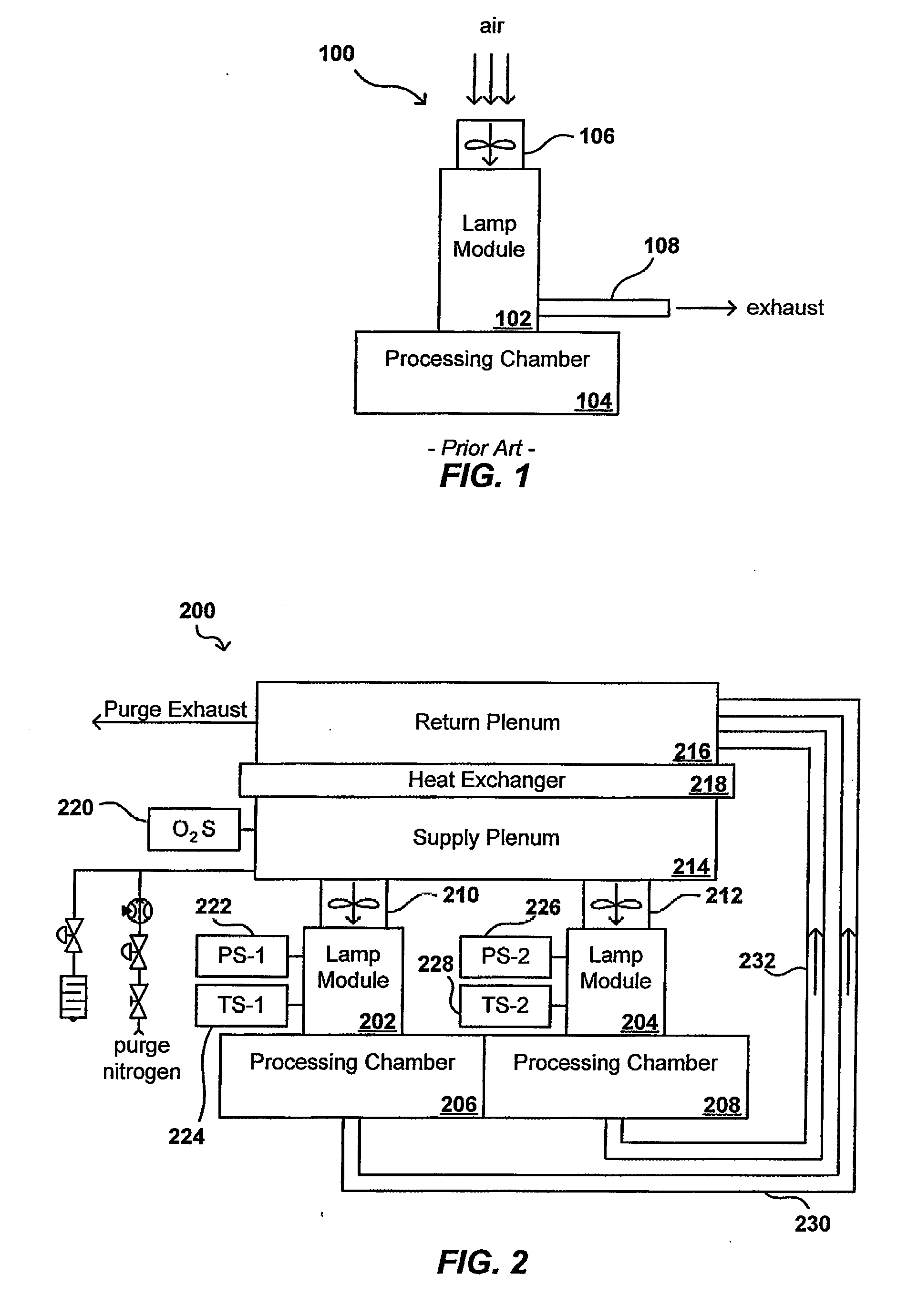
[0010]Systems and methods in accordance with various embodiments of the present invention provide for the re-circulation of a fluid in a UV curing system or device, such as by utilizing a re-circulation cooling system or closed-loop cooling system (CLCS). Such re-circulation can reduce the exhaust and seal requirements for the curing system. The use of a re-circulating fluid such as nitrogen also can reduce the production of ozone in the system, and can allow for operation of the curing system at lower wavelengths. Such re-circulation also can provide for the reduction of ozone concentration in the re-circulating fluid.
[0011]In one embodiment, a system for providing cooling for a UV curing system including a UV lamp source and a curing chamber includes a supply reservoir operable to contain a volume of fluid. A flow generating device, such as a blower, can direct a flow of fluid from the supply reservoir past the UV lamp source, such that the flow of fluid can remove heat energy from the UV lamp source. Return piping connected to the curing chamber can receive the heated flow of fluid and direct the flow of heated fluid to a return reservoir. A heat exchanger positioned along a flow path between the return reservoir and the supply reservoir can remove the heat energy from the heated flow of fluid, whereby the flow of fluid can be directed back into the supply reservoir to be re-circulated as a cooling fluid. The fluid can be any appropriate liquid or gas, such as a nitrogen gas or nitrogen-enriched gas. A gas separation module can be used that receives a flow of feed air and separates out at least one component of the feed air to generate a source of the fluid for the supply reservoir. The gas separation module can include a gas separation membrane, for example, which can receive a flow of feed air and produce a flow of nitrogen.
[0012]In one embodiment, an air module is provided for generating a re-circulating flow of cooling fluid for a radiation-based curing device. The module contains a supply reservoir operable to receive and contain a volume of fluid. A flow generating device can direct a flow of fluid from the supply reservoir to the radiation-based curing device, the flow of fluid operable to remove heat energy from the curing device. A return reservoir can receive the heated flow of fluid exiting the radiation-based curing device. The module also can include a heat exchanger positioned along a flow path between the return reservoir and the supply reservoir. The heat exchanger can remove heat energy from the heated flow of fluid and direct the flow of fluid back into the supply reservoir.
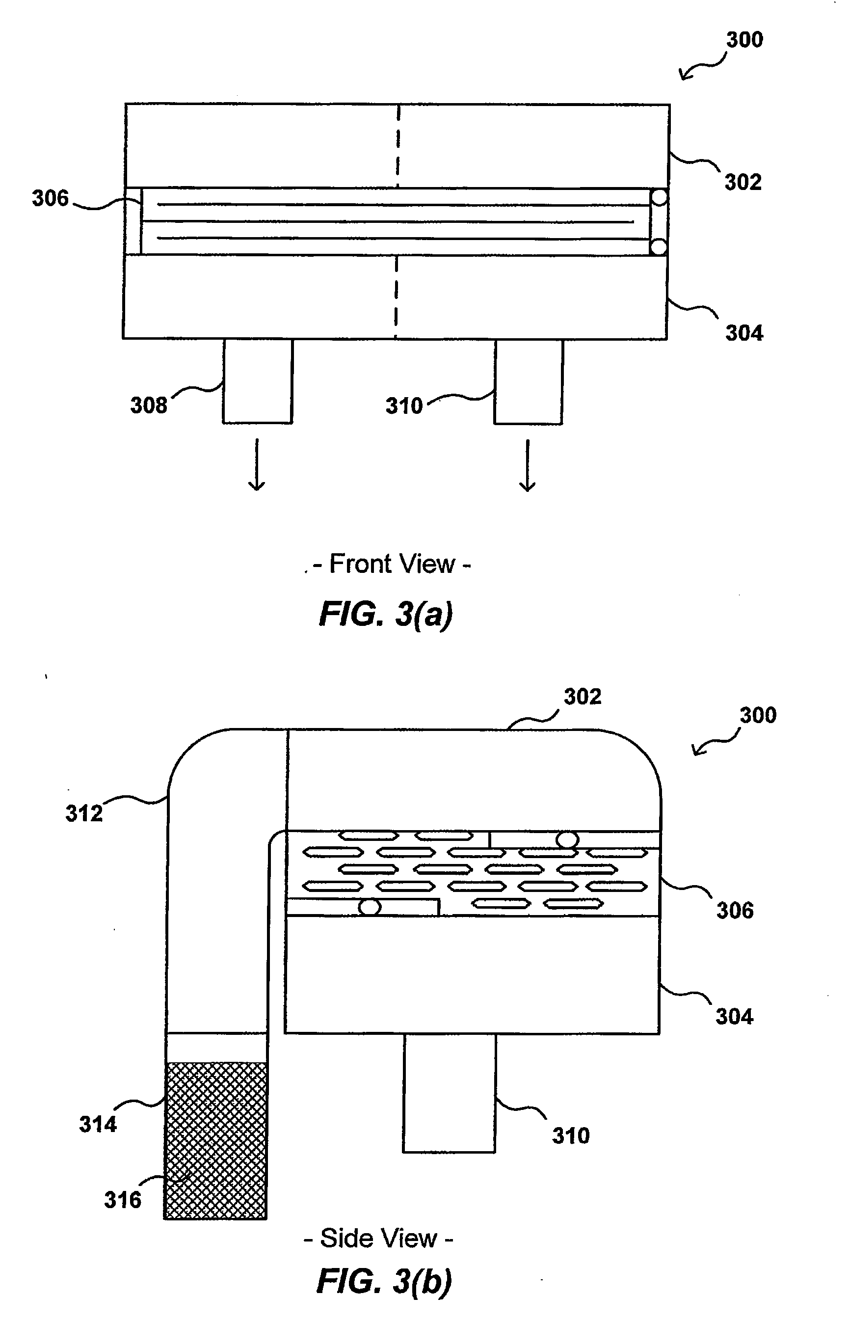
[0014]In one embodiment, a system for reducing the presence of ozone in a UV curing system includes a supply reservoir for containing a volume of fluid and a flow generating device operable to direct a flow of fluid from the supply reservoir past a UV lamp source, such that the flow of fluid can remove heat energy from the UV lamp source. A first run of piping connected to the curing chamber can receive the heated flow of fluid and direct the flow of heated fluid to an ozone destruction unit. The ozone destruction unit can receive the flow of heated fluid and reduce the concentration of ozone contained therein. A second run of piping connected between the ozone destruction unit and the supply reservoir then can direct the ozone-reduced flow of fluid hack into the supply reservoir. The ozone destruction unit can include a catalyst selected to cause a reaction with the heated flow of fluid that breaks down at least a portion of any ozone contained in the fluid. The catalyst can be any appropriate catalyst for breaking down ozone, such as is selected from the group consisting of MnO2 / CuO, MnO2 / CuO / Al2O3, activated carbon, Pd / MnO2, Pd / MnO2 / Silica-Alumina, MnO2 based catalysts, and precious metal pt / pd catalysts. The catalyst can be in the form of pellets contained in the ozone destruction device, or can be in the form of a coating on one of a honeycomb and a radiator device in the ozone destruction device.
[0016]In one embodiment, a method of reducing the presence of ozone in a UV curing tool includes receiving a flow of heated fluid exiting the UV curing tool. The flow of heated fluid is directed along a flow path having a length and shape such that the flow of fluid has a selected residence time in the flow path for a given flow rate. The flow path has a catalyst positioned on a surface thereof, or contained therein, whereby the flow of fluid in the flow path is in contact with the catalyst for the selected residence time. The catalyst is selected to cause a reaction with the flow of fluid that breaks down at least a portion of any ozone contained in the fluid. The ozone-reduced flow of fluid then is directed from the flow path back to the UV curing tool, whereby the flow of fluid can be re-circulated through the UV curing tool.

Problems solved by technology

Either of these forms of water incorporation is generally undesirable.
Also, in some particular CVD processes, thermally unstable or labile organic fragments of sacrificial materials (resulting from porogens used during CVD to increase porosity) need to be removed.
Conventional thermal anneal steps are generally of relatively long duration (e.g., often between 30 min to 2 hrs.) and thus consume significant processing time and slow down the overall fabrication process.
The use of UV radiation for curing and densifying CVD films can reduce the overall thermal budget of an individual wafer and speed up the fabrication process.
Because the UV sources used for curing tend to build up heat over time that can negatively impact the devices being processed and shorten the life of the sources themselves, there is a need to cool these existing UV and other curing sources, as well as to cool the electronics and various other components.
There are various downsides to such an approach.
One downside is that the heated air must be exhausted outside the system, adding cost and complexity to the exhaust apparatus for the overall processing line.
Another downside is that the use of ambient air leads to a substantial amount of oxygen leaking into the lamp module and / or curing chamber.
This effect can be mitigated to some extent by increasing the seal requirements for the curing system, but this again increases the cost and complexity of the curing system.
Another problem is that exposure of any oxygen in the system to UV radiation generates trace amounts of ozone in the system.
This ozone leads to consumption of the nitrogen in the system.
Further, there are strict requirements on the amount of ozone that can be present in such a system, and the continual generation of ozone during processing can lead to unacceptable levels of ozone that must be detected and addressed before processing can continue.

Method used


Image

  • Ozone abatement in a re-circulating cooling system
  • Ozone abatement in a re-circulating cooling system
  • Ozone abatement in a re-circulating cooling system

Examples


Embodiment Construction

[0033]Systems and methods in accordance with various embodiments of the present invention can overcome the aforementioned and other deficiencies in existing curing and other radiation-utilizing applications. In one embodiment, a cooling module is used to cool a radiation source (e.g., a UV lamp), the cooling module being operable to recirculate cooling fluid (e.g., nitrogen gas) through the source so as to reduce the load on the exhaust system for the production line or fabrication facility. The recirculation of a selected fluid, as opposed to the introduction of a flow of air into the system, also can provide for the reduction and / or elimination of seal requirements from users of the system, as the amount of the selected cooling fluid leaking into the system is less critical that for water vapor and feed air, which can include higher levels of oxygen, for example. The module can use a simple heat exchanger that utilizes cooling water (such as process water or another appropriate li...


PUM

PropertyMeasurementUnit
Flow rateaaaaaaaaaa
Concentrationaaaaaaaaaa
Volumeaaaaaaaaaa

Abstract

A re-circulating cooling system can be used with a curing system in order to reduce the exhaust requirements for the system. Further, using a cooling fluid such as nitrogen reduces the production of ozone and the sealing requirements for the system. A simple heat exchanger can be used between return and supply reservoirs in order to remove heat added to the re-circulating fluid during circulation past the curing radiation source. The nitrogen can come from a nitrogen source, or from a membrane or other device operable to split feed gas into its molecular components to provide a source of gas rich in nitrogen. An ozone destruction unit can be used with such a cooling system to reduce the amount of ozone to acceptable levels, and to minimize consumption of the nitrogen. A catalyst can be used to deplete the ozone that does not get consumed during the reaction.

Description

CROSS-REFERENCE TO RELATED APPLICATIONS[0001]This application claims priority to U.S. Provisional Application No. 60 / 816,800, entitled “Nitrogen Enriched Cooling Air Module for UV Curing System,” filed Jun. 26, 2006, which is hereby incorporated herein by reference. This application is also related to co-pending U.S. patent application Ser. No. ______, entitled “Nitrogen Enriched Cooling Air Module for UV Curing System,” filed concurrently with this application, Attorney Docket No. A 11181 / T74610, which is hereby incorporated herein by reference.BACKGROUND OF THE INVENTION[0002]Materials such as silicon oxide (SiOx), silicon carbide (SiC), and carbon doped silicon oxide (SiOCx) films find widespread use in the fabrication of semiconductor devices. One approach for forming such silicon-containing films on a semiconductor substrate is through the process of chemical vapor deposition (CVD) within a chamber. For example, a chemical reaction between a silicon supplying source and an oxyg...

Claims


Application Information

Patent Timeline
IPC IPC(8): B05D7/22
CPCB01D53/8675B01D2255/1023B05D3/067B01D2255/20761B05D3/0486B01D2255/2073
Inventor HO, DUSTIN W.ROCHA-ALVAREZ, JUAN CARLOSDU BOIS, DALE R.HENDRICKSON, SCOTT A.BALUJA, SANJEEVMUKUTI, NDANKA O.
Owner APPLIED MATERIALS INC
Learn More