Electronic device including a guest material within a layer and a process for forming the same
a technology of guest material and electronic device, which is applied in the direction of semiconductor devices, solid-state devices, electrical apparatus, etc., can solve the problems of low efficiency, low efficiency, and low efficiency of electronic components formed using the ink diffusion process, and achieves low intensities for commercially-sold displays
- Summary
- Abstract
- Description
- Claims
- Application Information
AI Technical Summary
Benefits of technology
Problems solved by technology
Method used
Image
Examples
example 1
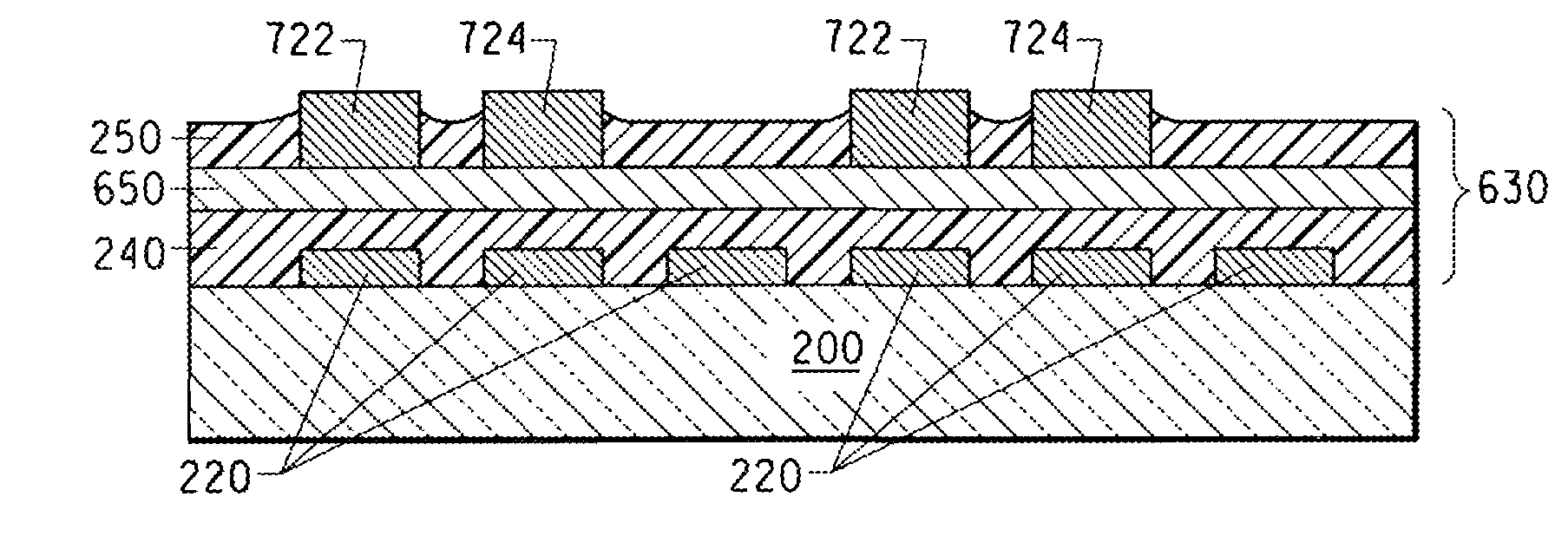
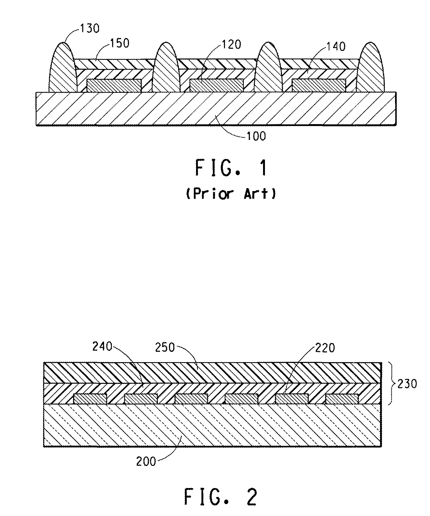
[0179] This Example demonstrates that appropriate manipulation of one or more physical properties of the organic active layer, and the liquid composition provides an electronic component in an electronic device without the need for a bank or well.
[0180] Electronic components are fabricated to include the following structure: ITO (first electrodes, or anodes) / buffer polymer / organic active / second electrode (cathode). The substrate is 30×30 mm (nominal) ITO coated glass. The charge-transport layer is a PEDOT material (BAYTRON-P™, Bayer AG, Germany). The organic active layers include a blue-emitting polyfluorene material (a host material capable of emitting blue light without any guest material). PEDOT is spin-coated onto a flat glass / ITO substrate at room temperature and then baked at approximately 200° C. for approximately 5 minutes. The film thickness is approximately 60-80 nm, as measured with a Dektec surface profiler. The blue-color organic active layer is then deposited from app...
example 2
[0184] This Example demonstrates that the processes described herein can be used to fabricate full color displays with a 200 micron pitch or greater.
[0185] An experiment similar to Example 1 is performed, using a full-color display with 300 micron pixel pitch, nominal. The diameter of the ink-jet nozzle is reduced to approximately 18 micron, and a display with multiple colors in a pre-defined pattern is produced using this smaller diameter nozzle. The diameter of the red, green, and blue-intermixed regions is reduced to approximately 65 micron. The thicknesses of the red, green, and blue-intermixed regions are in a range of approximately 60 to 90 nm. Therefore, the processes described herein can be used to fabricate full color displays with less than a 200 micron pitch.
example 3
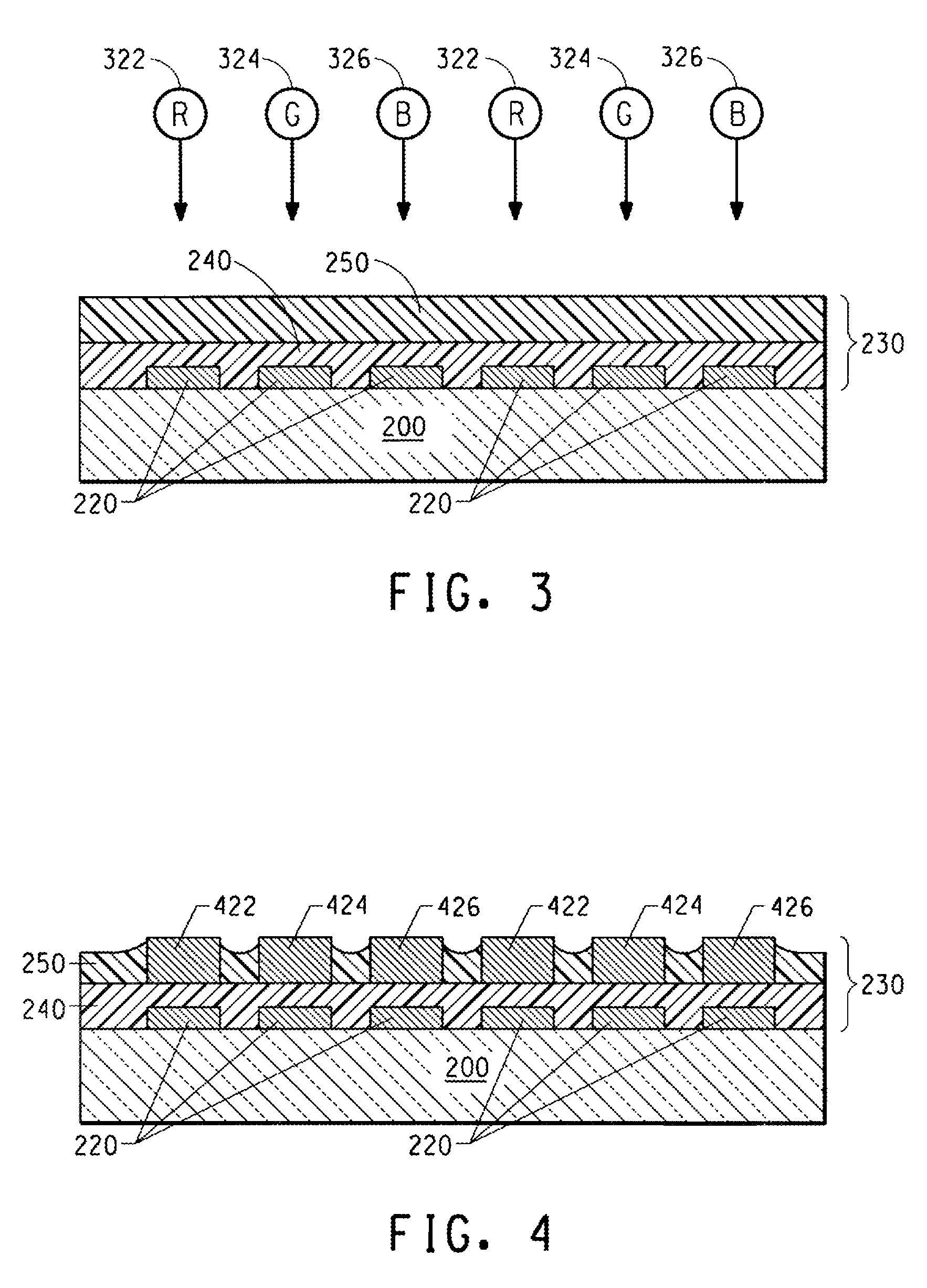
[0186] A full color display with red, green and blue polymer lines is produced using a procedure similar to that described in Example 1. An ink-jet printer with 40 nozzles is used for defining color pixels. The diameter of these nozzles is approximately 35 microns and the step motion between each drop is approximately 85 microns. The substrate is 100 mm×100 mm (4 inch×4 inch), nominal with a display area of approximately 80 mm×60 mm (3.2 inch×2.4 inch). The substrate does not include a well structure. The red, green and blue color stripes indicate: (1) a line pattern can be achieved without using bank structures, and (2) a full-color display can be made with 100 pixels-per-inch (equivalent to 254 micron pitch).
[0187] A full color, active matrix display is also fabricated with a substrate with thin-film-transistor pixel drivers. An organic active layer is constructed between the pixel drivers and the ITO contacts. As in Examples 1 and 2, a bank structure is not required for color in...
PUM
| Property | Measurement | Unit |
|---|---|---|
| weight percent | aaaaa | aaaaa |
| temperature | aaaaa | aaaaa |
| temperature | aaaaa | aaaaa |
Abstract
Description
Claims
Application Information
 - R&D
- Intellectual Property
- Life Sciences
- Materials
- Tech Scout
- Unparalleled Data Quality
- Higher Quality Content
- 60% Fewer Hallucinations
Browse by: Latest US Patents, China's latest patents, Technical Efficacy Thesaurus, Application Domain, Technology Topic, Popular Technical Reports.
© 2025 PatSnap. All rights reserved.Legal|Privacy policy|Modern Slavery Act Transparency Statement|Sitemap|About US| Contact US: help@patsnap.com


