
Method and apparatus for enhancing plasmon polariton and phonon polariton resonance

a technology of phonon polariton and plasmon polariton, applied in the field of optics, can solve the problems of affecting the energy density of vacuum leading to the emission of photons, affecting the ability of normal fluids, and affecting the detection accuracy of phonon polariton,

Active Publication Date: 2007-11-29
SOLARIS NANOSCI
View PDF17 Cites 15 Cited by
  • Summary
  • Abstract
  • Description
  • Claims
  • Application Information

AI Technical Summary

Benefits of technology

[0013] In one aspect, the invention relates to a method for generating a plasmon-polariton or phonon-polariton resonance effect including: providing a structure capable of such resonance; providing a gain medium; and placing the structure in close juxtaposition to the gain medium. In one embodiment the structure is a na

Problems solved by technology

Subsequent work by Fulling and Davies showed that a single accelerated mirror rather than an observer can result in an altering of the energy density of vacuum leading to the emission of photons.
However, the calculations showed that effective phonon temperatures of 1K required velocity gradients of 100 m / s per Angstrom, far beyond the capabilities of normal fluids.
This ingenious idea unfortunately predicts temperatures of 2-3K which are difficult to discern from stray mode coupling effects.
Unfortunately, the process behind the emission, Compton scattering of vacuum photons, is swamped by the enormous Brehmsstrahlung radiation predicted by the Bethe-Heitler formula.
Despite the large number of suggested schemes for observing the Unruh effect and the related non-adiabatic transformations of quantized electromagnetic vacuum modes, the process of popping a measurable number of photons out of the vacuum remains elusive to this day.

Method used


Image

  • Method and apparatus for enhancing plasmon polariton and phonon polariton resonance
  • Method and apparatus for enhancing plasmon polariton and phonon polariton resonance
  • Method and apparatus for enhancing plasmon polariton and phonon polariton resonance

Examples


Embodiment Construction

[0027] The invention will be more completely understood through the following detailed description, which should be read in conjunction with the attached drawings. Detailed embodiments of the invention are disclosed herein, however, it is to be understood that the disclosed embodiments are merely exemplary of the invention, which may be embodied in various forms. Therefore, specific functional details disclosed herein are not to be interpreted as limiting, but merely as a basis for the claims and as a representative basis for teaching one skilled in the art to variously employ the invention in virtually any appropriately detailed embodiment.

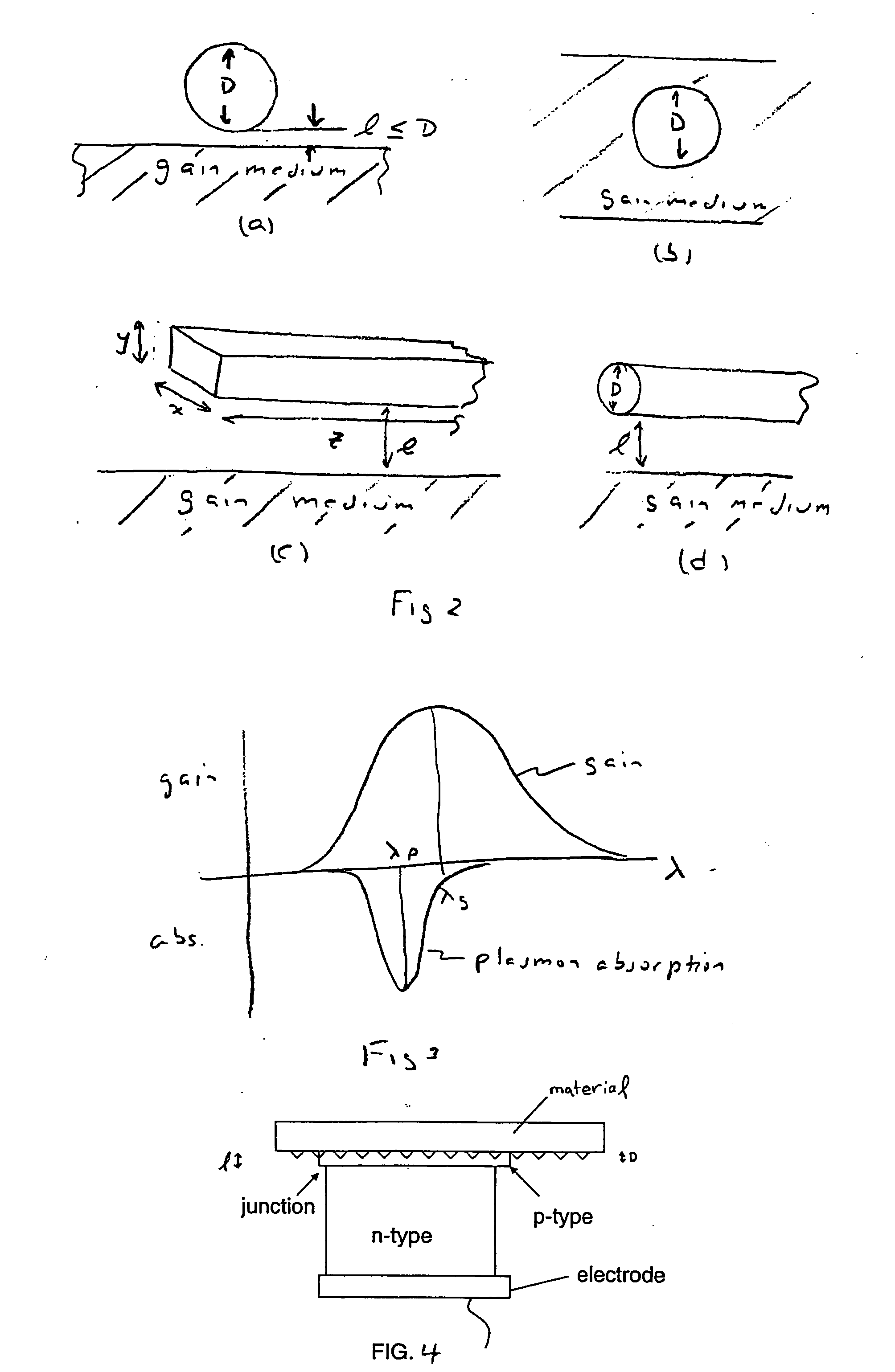
[0028] The invention herein relates to the use of the localized surface plasmon-polariton resonance on a surface in the presence of a gain medium. In one embodiment the surface is on a nanostructure that exhibits a greatly enhanced magnitude when the surrounding gain medium has gain near a critical value. In one embodiment this combination leads...


PUM


Abstract

A metallic nano-particle surrounded by an amplifying medium results in a boundary condition that creates a singularity in the particle's dynamic polarizability at the localized surface plasmon resonance and at a critical value of the gain is disclosed. The boundary condition may be time dependent due to excitation by a sub-picosecond laser pulse and couples to the electromagnetic vacuum resulting in photon emission in an analogue of the Unruh Effect. The vacuum emission from 2-D nanostructures embedded in high gain laser dyes predicts energies nearly two orders of magnitude larger than the spontaneous emission background. The vacuum radiation is may have a unique dependence on the excitation.

Description

RELATED APPLICATIONS [0001] This application is a Continuation-in-Part of U.S. patent application Ser. No. 11 / 100,339 filed Apr. 6, 2005 and entitled, “METHOD AND APPARATUS FOR ENHANCING PLASMON-POLARITON AND PHONON POLARITON RESONANCE,” which claims benefit under 35 U.S.C. §119(e) to U.S. Provisional Application No. 60 / 559,791 filed Apr. 6, 2004, and entitled “PLASMON ENHANCEMENT BY AMPLIFYING MEDIA,” and to U.S. Provisional Application No. 60 / 565,754 filed Apr. 27, 2004 and entitled, “PLASMON ENHANCEMENT BY ACTIVE MEDIA,” and to U.S. Provisional Application No. 60 / 576,215 filed Jun. 2, 2004 and entitled, “LOCALIZED SURFACE PLASMON SINGULARITIES IN AMPLIFYING MEDIA,” and claims the benefit under 35 U.S.C. § 119(e) to U.S. Provisional Application No. 60 / 780,746 filed Mar. 9, 2006, and entitled “SCATTERING OF VACUUM STATES BY DYNAMIC PLASMON SINGULARITIES,” the entire disclosures of each of which are hereby incorporated herein by reference for all purposes.FIELD OF THE INVENTION [000...

Claims


Application Information

Patent Timeline
IPC IPC(8): G02F1/01
CPCB82Y20/00G01N21/658G02F1/353H01S5/1046G02F2203/10H01S3/213G02F2202/36
Inventor LAWANDY, NABIL M.
Owner SOLARIS NANOSCI
Learn More