
Picosecond Terawatt CO2 laser amplification system and method based on Raman frequency shift difference frequency

A picosecond laser and laser amplification technology, which is applied to lasers, laser components, and lasers using scattering effects, etc., can solve the problems of discrete and discontinuous spectral lines, difficulties in laser seed light amplification, etc., to increase bandwidth and overcome small signal gain Difficulty amplifying and reducing the effect of the period of the pulse train

Inactive Publication Date: 2020-01-10
HUAZHONG UNIV OF SCI & TECH
View PDF1 Cites 1 Cited by
  • Summary
  • Abstract
  • Description
  • Claims
  • Application Information

AI Technical Summary

Problems solved by technology

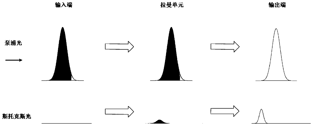
[0007] Aiming at the defects of the prior art, the object of the present invention is to provide a picosecond terawatt CO based on Raman frequency shift difference frequency 2 Laser amplification system and method, aiming to solve the picosecond terawatt CO 2 It is extremely difficult to amplify laser seed light, and the technical problems of discrete and discontinuous spectral lines

Method used


Image

  • Picosecond Terawatt CO2 laser amplification system and method based on Raman frequency shift difference frequency
  • Picosecond Terawatt CO2 laser amplification system and method based on Raman frequency shift difference frequency
  • Picosecond Terawatt CO2 laser amplification system and method based on Raman frequency shift difference frequency

Examples


Embodiment Construction

[0033]In order to make the object, technical solution and advantages of the present invention clearer, the present invention will be further described in detail below in conjunction with the accompanying drawings and embodiments. It should be understood that the specific embodiments described here are only used to explain the present invention, not to limit the present invention. In addition, the technical features involved in the various embodiments of the present invention described below can be combined with each other as long as they do not constitute conflicts with each other.

[0034] The embodiment of the present invention provides a picosecond terawatt CO based on the difference frequency of Raman frequency shift 2 Laser amplification system, including solid-state picosecond laser generator, Raman frequency shifter, difference frequency crystal and cross-flow CO 2 Laser amplifier; a part of the picosecond laser pulse generated by the solid-state picosecond laser gener...


PUM

PropertyMeasurementUnit
lengthaaaaaaaaaa
areaaaaaaaaaaa
areaaaaaaaaaaa

Abstract

The invention discloses a picosecond Terawatt CO2 laser amplification system and method based on Raman frequency shift difference frequency. The system comprises a solid picosecond laser generator, aRaman frequency shifter, a difference frequency crystal and a cross-flow CO2 laser amplifier. One part of picosecond laser pulses generated by the solid picosecond laser generator enter the Raman frequency shifter, the other part of the picosecond laser pulses is injected into the difference frequency crystal together with output light pulses of the Raman frequency shifter to generate seed light,and the seed light is amplified through the cross-flow CO2 laser amplifier. The method comprises the following steps: picosecond laser pulses generated by a solid picosecond laser generator generate Raman frequency shift, and light pulses of a first Stocks sideband are obtained; the obtained light pulses and a reference picosecond pulse are injected into a difference frequency crystal to obtain seed light; and the obtained seed light is injected into a cross-flow CO2 amplifier and amplified in the cross-flow CO2 amplifier. The technical problem that picosecond Terawatt CO2 laser seed light isextremely difficult to amplify and the spectral lines are discrete and discontinuous in the prior art can be solved.

Description

technical field [0001] The invention belongs to the field of ultra-powerful laser technology, and more specifically relates to a picosecond terawatt CO based on Raman frequency shift difference frequency 2 Laser amplification system and method. Background technique [0002] CO 2 Laser-driven ion accelerators can reduce the size and cost of accelerators by orders of magnitude while ensuring high-quality ion beams suitable for medical and material science applications. Among them, light ion beams (He, N, C, O, Ne) It is the best tool for the treatment of advanced hypoxic and radiation-resistant tumors. Laser-driven particle accelerators rely on energy transfer from a relatively focused laser beam to electrons in plasma or vacuum, and the maximum converted laser energy is given by the mass-motive force (Iλ 2 , I is the laser intensity) decision. Due to the greater mass dynamics brought by long wavelengths, long wavelengths combined with large-size focus points are a major r...

Claims


Application Information

Patent Timeline
Patent Type & Authority Applications(China)
IPC IPC(8): H01S3/30H01S3/10
CPCH01S3/10007H01S3/305
Inventor 唐霞辉李想夏燃肖瑜宋宇燕胡聪秦应雄万辰皓彭浩
Owner HUAZHONG UNIV OF SCI & TECH
Learn More