
Picosecond laser apparatus and methods for its operation and use

a laser and laser technology, applied in the field ofpicosecond laser apparatus and methods for its operation and use, can solve the problems of inability to change from photothermal to photomechanical processes, and inability to operate normally, etc., and achieve the effect of short duration and high energy

Active Publication Date: 2008-02-07
CYNOSURE
View PDF3 Cites 27 Cited by
  • Summary
  • Abstract
  • Description
  • Claims
  • Application Information

AI Technical Summary

Benefits of technology

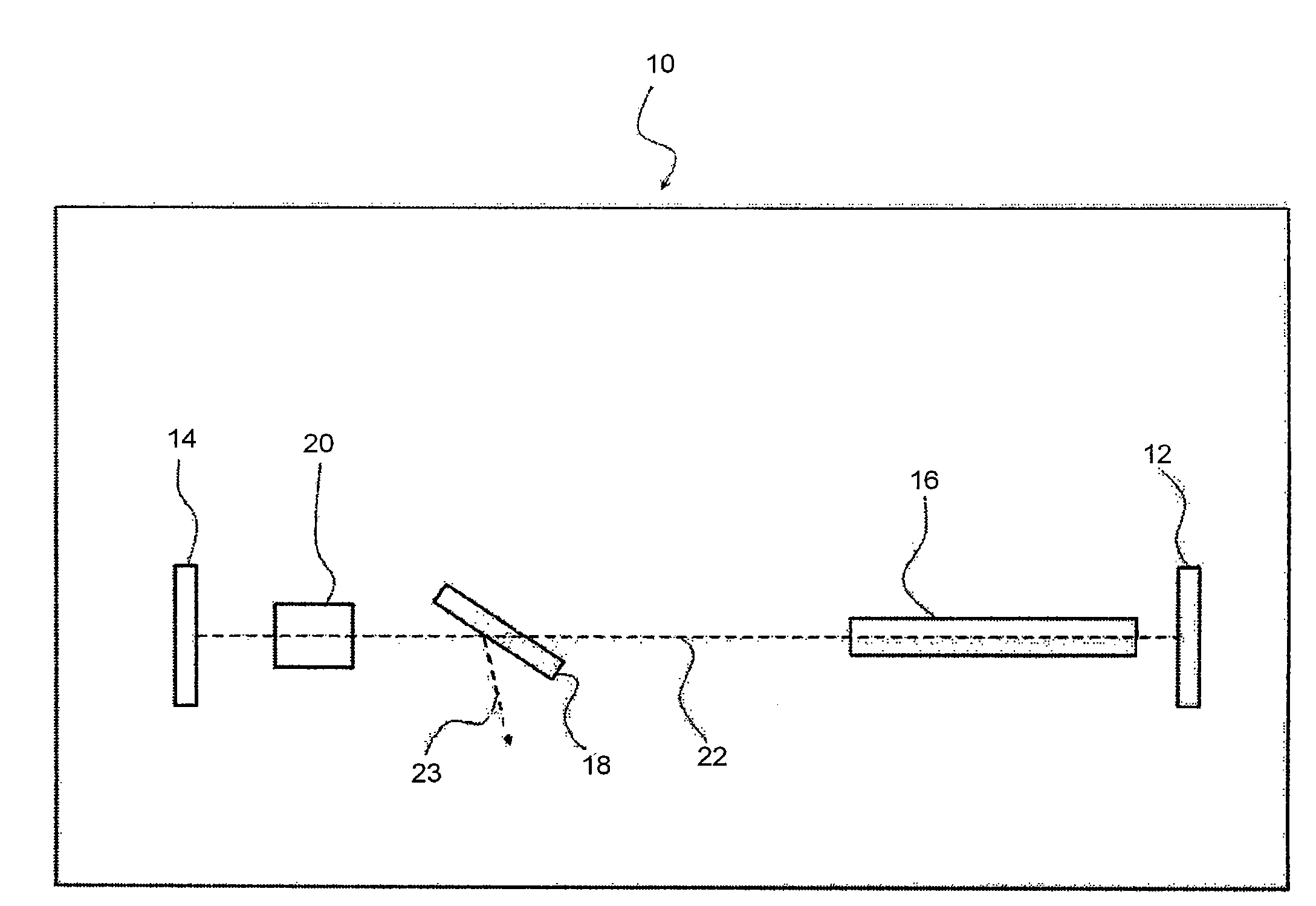
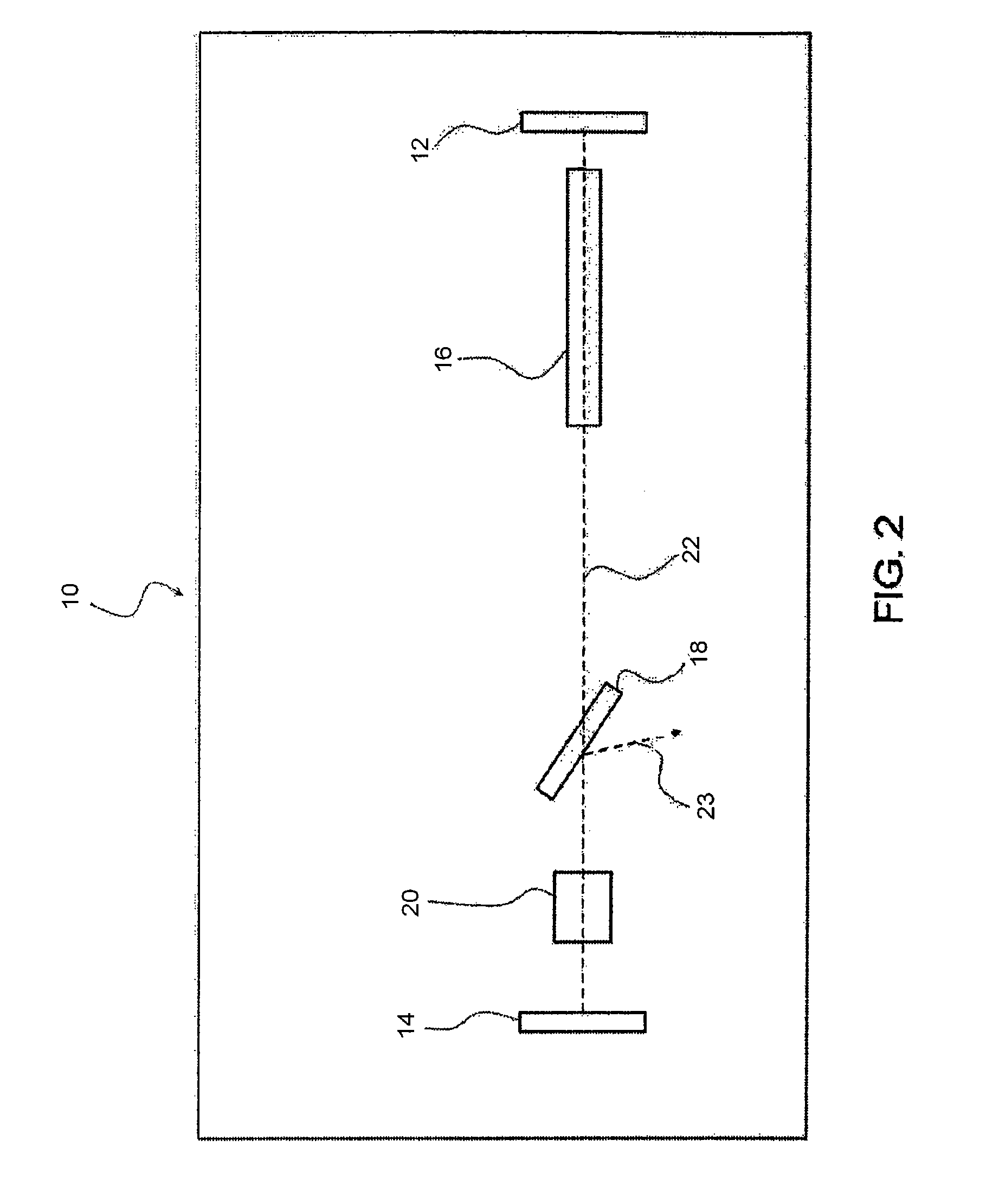
[0012]In addition to requiring only a single resonator and lasing (or gain) medium, apparatuses may be further simplified in that, in a first operating mode, a modelocked pulse is established in the resonator, without the use of an additional modelocking device such as an acousto-optic modulator. Moreover, the need to adjust resonator length, associated with the use of some acousto-optical devices, is eliminated. The overall component and operating requirements of apparatuses according to embodiments of the present invention are therefore considerably simplified. For example, in some cases only four optical components may be required, as is common in many Q-Switched laser systems.
[0015]In a subsequent, second mode of operation, the modelocked pulse is amplified. In the case where the electro-optical device is positioned between the polarizer and one of the mirrors (arbitrarily denoted the “second” mirror) a first (constant) bias voltage may be applied to the electro-optical device such that a pulse reflected at this second mirror traverses the polarizer substantially without loss of intensity or amplitude. To extract the energy from the amplified pulse, a second (constant) bias voltage may thereafter be applied to the electro-optical device such that the polarizer substantially expels a pulse reflected at the second mirror from the resonator. This releases the pulsed laser energy having the desired characteristics described herein.
[0021]The voltage waveform electronics may be used for initially applying the baseline voltage, Vo, to the electro-optical device, prior to applying the time-dependent differential voltage, δV(t), which establishes a first, modelocked operating mode, as discussed above. Subsequently, the voltage waveform electronics can apply a first (constant) bias voltage (e.g., zero voltage or complete discharge of the electro-optical device), such that a reflected pulse at the second mirror traverses the polarizer substantially without loss of intensity. Under these conditions the lasing or gain medium amplifies the laser energy within the resonator, in a second, amplification operating mode, prior to its extraction or release from the apparatus as laser energy having the desirable pulse characteristics, including the short pulse duration and high pulse energy discussed above. This generation of such laser energy, for applications discussed herein, is ultimately effected by applying a second bias voltage (e.g., the quarter wave voltage) to the electro-optical device, such that a pulse reflected at the second mirror is substantially expelled from the resonator at the polarizer.

Problems solved by technology

The fluence must, however, be limited to avoid denaturing tissues surrounding the targeted area.
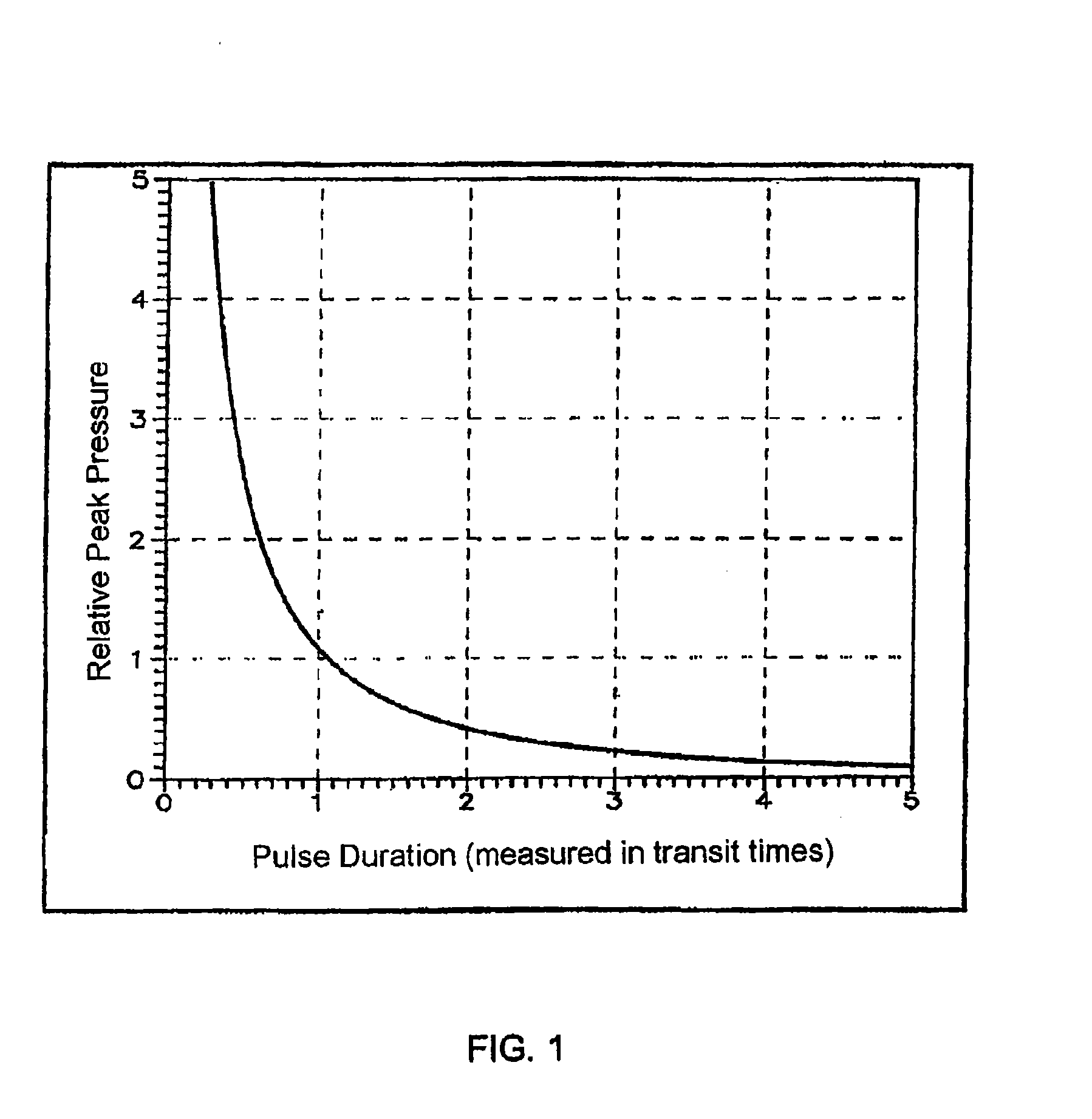
The pulse duration and pulse intensity, for example, can impact the degree to which laser energy diffuses into surrounding tissues during the pulse and / or causes undesired, localized vaporization.
The use of even shorter pulses, however, results in a change from photothermal to photomechanical processes.
Unfortunately, current systems capable of such short pulse duration and high energy output are too complex and / or expensive for practical use in the treatment or removal of tattoos and other pigmentations.
Also, because the system utilizes the separate operation of two resonators, it is possible due to component limitations for radiation from one resonator to leak or “spill over” into another.
A consequence of this is the generation of undesirable or “parasitic” pulses, particularly in the resonator used for amplification, which supports a significantly lower threshold for laser oscillation.
The simpler alexandrite and other Q-switched lasers currently employed in the treatment of dermatological pigmentations cannot reliably achieve tattoo pigment particle clearance in a matter of only a few treatments, despite claims to the contrary.

Method used


Image

  • Picosecond laser apparatus and methods for its operation and use
  • Picosecond laser apparatus and methods for its operation and use
  • Picosecond laser apparatus and methods for its operation and use

Examples


example 1

[0070]A laser apparatus as described herein is used to generate pulsed laser energy having a pulse duration of about 100-200 ps with about 500-750 mj / pulse. The laser apparatus includes a resonator with two substantially totally reflective mirrors at opposite ends of its optical axis. An alexandrite crystal lasing medium, a polarizer, and a Pockels cell are positioned along this optical axis. An optical flashlamp is also included for pumping the alexandrite lasing medium, which generates laser energy having a wavelength in the range of 700-950 nm.

[0071]The pulsed laser energy described above is generated by pumping the lasing medium and first establishing a modelocked pulse oscillating in the resonator. In the modelocked pulse operating mode, a time-dependent voltage waveform, as described herein, is applied to the Pockels cell. This waveform results from the sum of a constant baseline voltage and a time-dependent differential voltage. The baseline voltage is in the range of 1000-15...


PUM


Abstract

Apparatuses and methods are disclosed for applying laser energy having desired pulse characteristics, including a sufficiently short duration and / or a sufficiently high energy for the photomechanical treatment of skin pigmentations and pigmented lesions, both naturally-occurring (e.g., birthmarks), as well as artificial (e.g., tattoos). The laser energy may be generated with an apparatus having a resonator with the capability of switching between a modelocked pulse operating mode and an amplification operating mode. The operating modes are carried out through the application of a time-dependent bias voltage, having waveforms as described herein, to an electro-optical device (e.g., a Pockels cell) positioned along the optical axis of the resonator.

Description

FIELD OF THE INVENTION[0001]The present invention relates to apparatuses and methods for delivering laser energy having a short pulse duration (e.g., less than about 1 nanosecond) and high energy output per pulse (e.g., greater than about 250 millijoules). The desired operating parameters are achieved through the application of a bias voltage, having a time-dependent value as described herein, to an electro-optical device such as a Pockels cell. The Pockels cell may be disposed in a single laser having a resonator that can be operated in two modes, depending on the bias voltage applied to the electro-optical device. As a result, laser energy suitable for a number of applications, including treating and removing pigment particles such as those introduced to the human body as tattoos, may be generated using a relatively simple apparatus.BACKGROUND OF THE INVENTION[0002]Lasers are recognized as controllable sources of radiation that is relatively monochromatic and coherent (i.e., has l...

Claims


Application Information

Patent Timeline
IPC IPC(8): H01S3/115
CPCA61B18/203A61B2017/00769A61B2018/00452A61B2018/0047H01S3/115H01S3/107H01S3/1103H01S3/1109G02F1/0327H01S3/00A61N5/067A61N5/0616
Inventor SIERRA, RAFAEL ARMANDOMIRKOV, MIRKOWELCHES, RICHARD SHAUN
Owner CYNOSURE
Learn More