Catheter tubing, catheter, and catheter assembly

Inactive Publication Date: 2009-02-26
PUHASMAGI ARNE +2
View PDF13 Cites 57 Cited by
  • Summary
  • Abstract
  • Description
  • Claims
  • Application Information

AI Technical Summary

Benefits of technology

[0007]on one hand through the development of a catheter tubing and of a catheter made of such catheter tubing, which is more kind to the patient's skin in the region of said fistulas and therefore more fitted to be employed as a fistula catheter, and / or provides an opportunity to make the total time duration for each dialyse shorter, and
[0022]Advantageously, the above mentioned avenues of development can be combined in the catheter assembly according to the invention. Thus, the catheter in the catheter assembly according to a preferred embodiment of the invention at least partly consists of a hydrophilic plastic material which swells significantly in contact with liquids of the human body, including blood. Preferably, the catheter consists of a catheter according to the invention. Therefore the outer diameter of the catheter, according to this preferred embodiment, initially is smaller than the diameter of the opening in the front end of the hub, such that the outer diameter of the catheter can expand through swelling in use without obstacle caused by the hub in the region of the opening. Suitably, the diameter of the opening is so much larger than the catheter that the catheter will completely fill the opening due to swelling without constriction by the hub material in the region of the opening.

Problems solved by technology

The frequent penetration of the fistula and the damage caused by the mechanical contact by the catheters make the fistula age so that it gets ripple.
When they are all aged, more dangerous dialysis methods must be used as a last care.
Plastic catheters are generally known and have in comparison with catheters made of steel the advantage that they are softer, but they do not satisfy ever increasing demands as far as care of the skin of the patient are concerned when used as fistula catheters.
It is a typical feature of these members, however, that they are not mounted on or form an integrated part of the hub that constitutes a separate unit which is mounted on the catheter itself, which does not promote a care handling of the assembly during the penetration of the patient's skin or during the continued treatment.

Method used


Image

  • Catheter tubing, catheter, and catheter assembly
  • Catheter tubing, catheter, and catheter assembly
  • Catheter tubing, catheter, and catheter assembly

Examples


Embodiment Construction

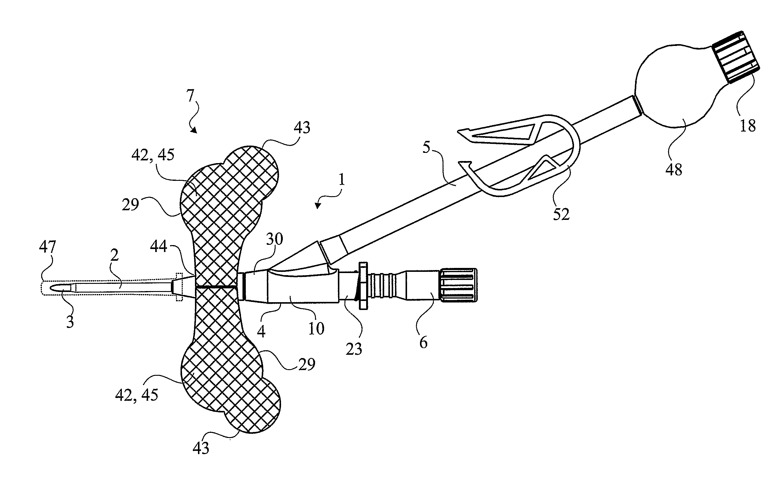
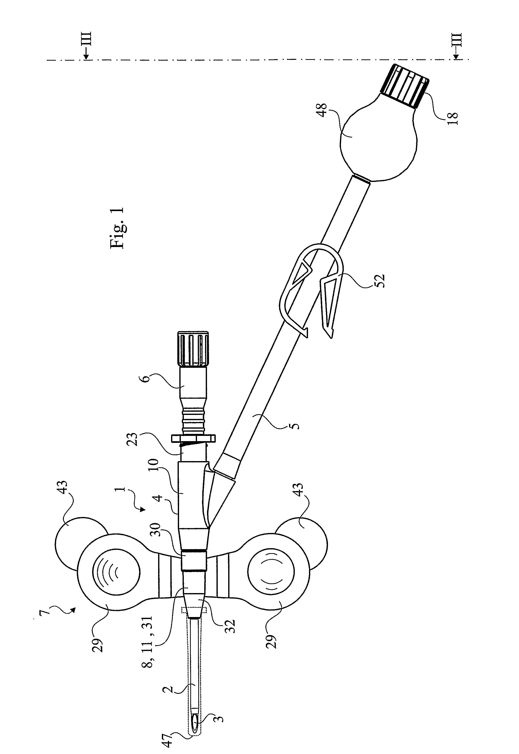
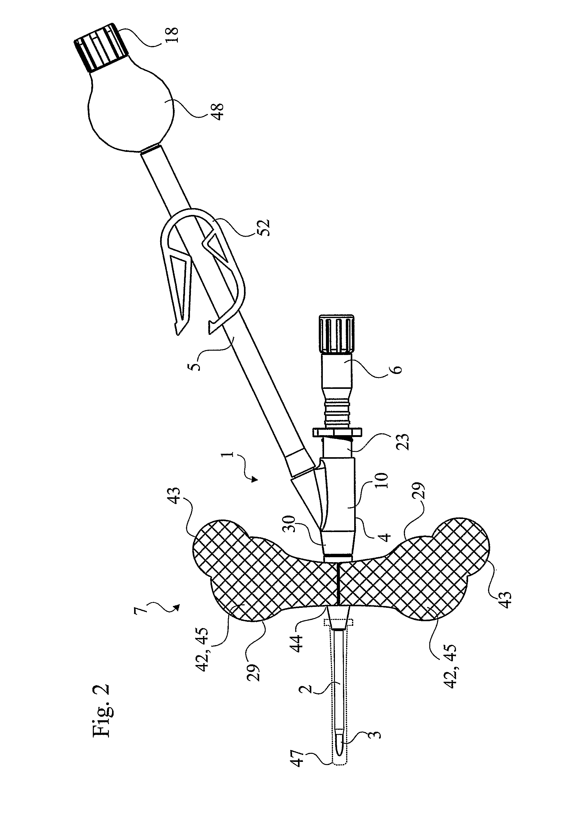
[0006]Even if a catheter designed according to the invention can be employed also for other purposes than as a fistula catheter, the invention in the first place aims at providing an improved fistula catheter and a catheter tubing intended for such type of a catheter. In connection herewith it is a purpose of the invention to make a delay of the aging of the fistulas possible. This can be achieved according to the invention along two avenues of development, namely;[0007]on one hand through the development of a catheter tubing and of a catheter made of such catheter tubing, which is more kind to the patient's skin in the region of said fistulas and therefore more fitted to be employed as a fistula catheter, and / or provides an opportunity to make the total time duration for each dialyse shorter, and[0008]on the other hand by designing the assembly described in the preamble in such a mode that it promotes a careful penetration of the fistula wall and also such that it substantially pre...


PUM

PropertyMeasurementUnit
Temperatureaaaaaaaaaa
Fractionaaaaaaaaaa

Abstract

A catheter tubing (2) consists of a composite comprising a first material (54) which mainly consists of a hydrophilic plastic material which absorbs moisture and which therefore swells in contact with e.g. blood, and a second material which essentially does not absorb moist but which forms reinforcing longitudinal strands (55) in the catheter tubing, which counteract that the catheter tubing is extended or becomes thicker because of the swelling capacity of the first polymeric material, such that the volume increase of the hydrophilic, first plastic material substantially results in an increase of the circumference of the tubing and hence of its diameter and flow area. A catheter is made of a catheter tubing of that type and can be included in an assembly (1) comprising a hub (4) having a front portion (11) provided with a pair of wings (29) extending outwards from the hub. The wings can be folded against one another in order to serve as a gripping member (7) provided adjacent to the catheter when the catheter is being inserted into a fistula (40), whereupon they can be brought to contact and be releasably adhered to the skin of a patient.

Description

TECHNICAL FIELD[0001]The invention relates to a catheter tubing, which means a tubing intended to be used for the manufacturing of catheters, and a catheter made of such catheter tubing, particularly for hemo-dialysis.[0002]The invention also relates to a catheter assembly, which may comprise a catheter of that type, particularly a fistula catheter, but which alternatively may comprise other catheters than fistula catheters for hemo-dialysis. The assembly in both cases comprises a proximate conduit and a hub forming a connection between the catheter and the proximate conduit for conveying blood or other liquid to or from a patient, said hub comprising a rear portion through which there extends a straight passageway, which is coaxial with an end portion of the catheter, which is connected to the hub, and a branch conduit to which said proximate conduit is or can be connected, and a distal portion in front of the mouth of said branch conduit. Particularly, the invention concerns a fis...

Claims


Application Information

Patent Timeline
IPC IPC(8): A61M25/02A61M25/00A61M25/18
CPCA61L29/06A61L29/126A61M25/0043A61M25/0097A61M25/0606A61M25/02C08L75/04A61M1/3661A61M39/10
Inventor PUHASMAGI, ARNESVEDBERG, MICHAELGRINNEBACK, KAY
Owner PUHASMAGI ARNE
Why Eureka
Try Eureka