
Semiconductor Device and Manufacturing Method Thereof

a semiconductor and manufacturing method technology, applied in the field of semiconductor elements, can solve the problems of difficult control of impurity concentration profiles, inability to simplify the manufacture of semiconductor elements, and breakage of elements, so as to reduce the series resistance of a substrate, increase the operating speed of an element, and facilitate the effect of obtaining

Inactive Publication Date: 2007-11-01
FOUND FOR ADVANCEMENT OF INT SCI
View PDF11 Cites 4 Cited by
  • Summary
  • Abstract
  • Description
  • Claims
  • Application Information

AI Technical Summary

Benefits of technology

[0015] It is an object of this invention to solve these problems, enables introduction of a thin semiconductor layer that cannot be achieved by the prior art, reduces the series resistance of a substrate, increases the operating speed of an element, makes it possible to easily obtain a substrate with an impurity concentration profile controlled in advance before manufacturing an element, and reduces the manufacturing cost of a semiconductor element.

Problems solved by technology

If the thickness is further reduced, there has arisen a problem that the mechanical strength is reduced to thereby cause breakage of the element, or the like.
However, the high temperature of 800° C. or more is used, there has arisen a problem of diffusion of metal atoms into the semiconductor layer and further arisen a problem that it is quite difficult to control an impurity concentration profile when forming the foregoing epitaxial layer in multilayers in advance and thus only the single semiconductor layer or the two-layer stacked semiconductor layers can be obtained, and therefore, the manufacture of a semiconductor element cannot be simplified.
With respect to a conventional vertical-type semiconductor element, it has been difficult to form an element having both n-type and p-type polarities in a vertical direction and, in the case of forming a semiconductor circuit such as an inverter, it is formed by mounting individual semiconductor elements on a wiring board.
Referring back to the formation of the semiconductor element, a number of processes such as impurity ion implantation and diffusion are required for forming the semiconductor element and many of them require a thermal process near 1000° C., and therefore, it is difficult to control the impurity distribution in the element and thus the yield is reduced, thereby causing a problem that the element increases in price.
Since only the {100} plane can be used as a substrate plane orientation in terms of manufacturing technology, there has arisen a problem that the diffusion constants of electrons and holes are small and thus it is not possible to increase the speed of current conduction or interruption of the element.
Further, since the element is formed on the silicon substrate, the generated heat of the element is difficult to dissipate to the outside of the element and thus the temperature of the element rises and, therefore, there has arisen a problem that electrons or holes extremely increase, thereby causing thermal malfunction of the element or requiring a complicated temperature compensation circuit.
Further, since it has conventionally been difficult to form a plurality of vertical-type semiconductor elements on a single semiconductor substrate, there has arisen a problem that a semiconductor device formed using these semiconductor elements increases in size.
The foregoing problem that the semiconductor device increases in size due to incapability of integration has caused a problem that wiring connecting the adjacent semiconductor elements increases in distance and thus has caused a problem that the parasitic capacitance and inductance possessed by the wiring increase to disable speed-up of the semiconductor device.

Method used


Image

  • Semiconductor Device and Manufacturing Method Thereof
  • Semiconductor Device and Manufacturing Method Thereof
  • Semiconductor Device and Manufacturing Method Thereof

Examples


embodiment 1

[0046] The structure and manufacturing method of a semiconductor substrate according to embodiment 1 of this invention will be described hereinbelow with reference to FIG. 3. A conductivity type referred to hereinbelow represents an n-type or a p-type of a silicon semiconductor and a change in impurity concentration is also included in a difference in conductivity type. FIG. 3 shows a sectional structure of a bipolar transistor substrate according to this embodiment. In FIG. 3, the bipolar transistor substrate comprises a Si layer 101 having a first conductivity type for forming an emitter layer, a Si layer 102 having a conductivity type opposite to the first conductivity type as a second conductivity type for forming a base layer, a Si layer 103 having a third conductivity type for forming a collector layer, a Si layer 104 having a fourth conductivity type for forming a collector electrode contact region, a metal substrate 108 connected to the Si layer having the fourth conductivit...

embodiment 2

[0064] The structure of a semiconductor substrate according to embodiment 2 of this invention will be described with reference to FIG. 6. FIG. 6 shows a vertical-type MOSFET substrate in this embodiment 2, wherein it comprises, on a metal substrate 401, a high-concentration drain layer 403 having a first conductivity type, a drain layer 404 having a second conductivity type which differs from the first conductivity type in impurity concentration, and a body layer 405 having a third conductivity type being a conductivity type opposite to the first conductivity type and used for forming a MOSFET channel. These layers are formed on a silicon substrate having a {110} plane by the same method as that shown in embodiment 1.

[0065] The conductivity types, impurity concentrations, and thicknesses of the respective layers are set to n-type, 1×1020 cm−3, and 0.2 μm for the high-concentration drain layer, n-type, 2×1017 cm−3, and 0.5 μm for the drain layer, and p-type, 5×1018 cm−3, and 0.2 μm ...

embodiment 3

[0086] The structure of a semiconductor substrate according to embodiment 3 of this invention will be described with reference to FIG. 8. FIG. 8 shows a vertical-type IGBT substrate in this embodiment 3, wherein it comprises, on a metal substrate 601, an anode layer 603 having a first conductivity type, a buffer layer 604 having a second conductivity type opposite to the first conductivity type, a conductivity modulation layer 605, and a gate layer 606 having a third conductivity with the same polarity as that of the anode layer. These layers are formed on a silicon substrate having a {110} plane by the same method as that shown in embodiment 1. In this embodiment, the conductivity types, impurity concentrations, and thicknesses of the respective layers are set to p-type, 1×1020 cm−3, and 0.2 μm for the anode layer, n-type, 1×1020 cm−3, and 0.2 μm for the buffer layer, n-type, 2×1017 cm−3, and 0.2 μm for the conductivity modulation layer, and p-type, 5×1018 cm−3, and 0.2 μm for the ...


PUM

PropertyMeasurementUnit
thicknessaaaaaaaaaa
temperatureaaaaaaaaaa
thicknessaaaaaaaaaa

Abstract

As a substrate for a semiconductor device, a metal substrate is used, and the metal substrate is composed of a metal base body made of a first metal and a connecting metal layer made of a second metal for covering the metal base body. The substrate has a structure wherein a diffusion preventing layer for preventing diffusion of the first metal is provided on the connecting metal layer.

Description

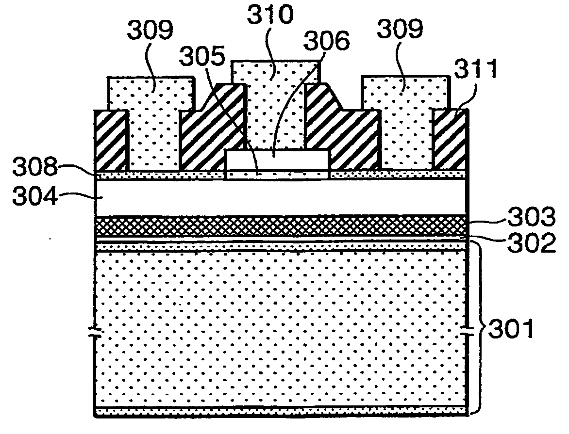
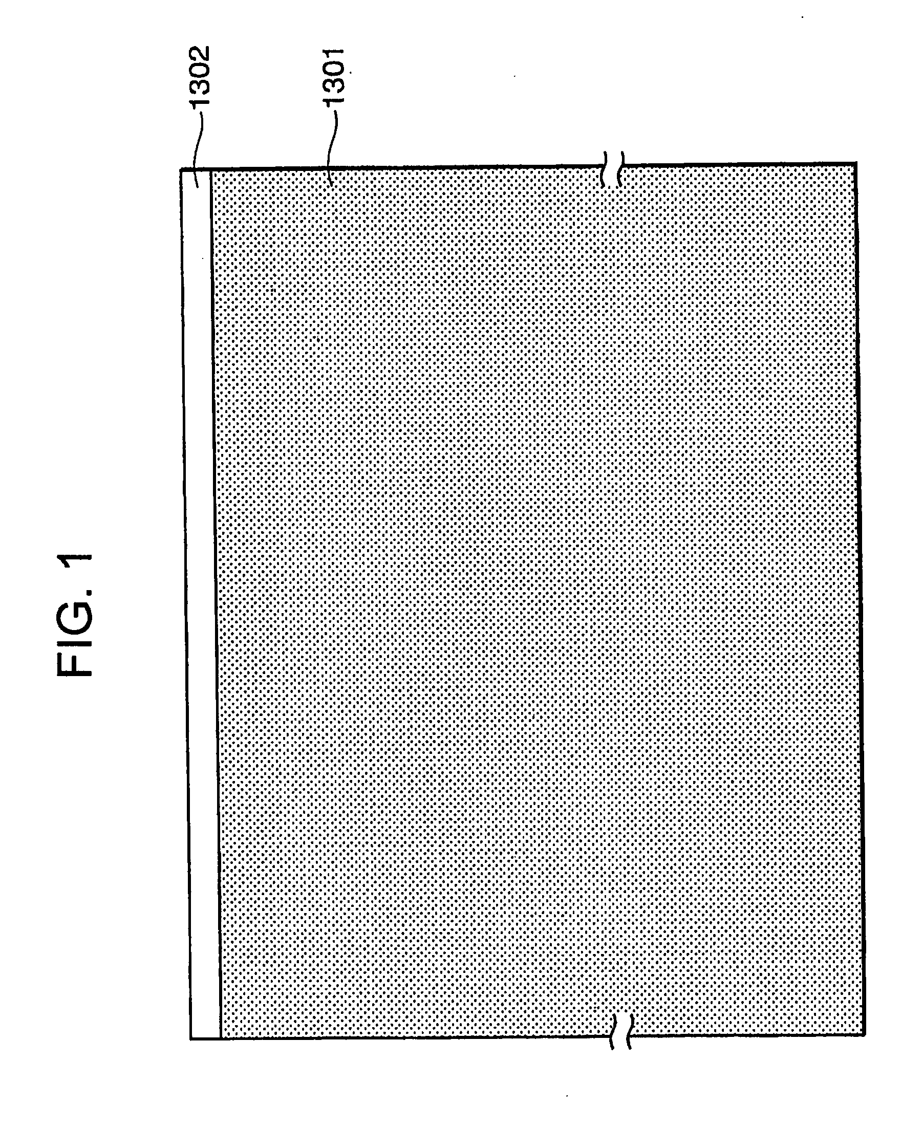
TECHNICAL FIELD [0001] This invention relates to a semiconductor element that operates at high speed and high power, and a manufacturing method thereof. BACKGROUND ART [0002] High-speed transistors adapted to operate in a microwave band and high-power transistors for use in power conversion are applied to various fields such as household electrical appliances. [0003] As a semiconductor element forming a high-speed transistor or a high-power transistor, there is a bipolar transistor, a thyristor, a GTO, an IGBT, a MOSFET, or the like. Such an element is required to turn on / off the high power at high speed in response to a pulse signal and, thus, for the purpose of satisfying both supply voltage resistance and speediness, use has been made of a semiconductor substrate that differs from an integrated circuit substrate formed in a flat shape. [0004] As the semiconductor substrate that has been used for forming such an element, use has been made, as shown in FIG. 1, of a two-layer struct...

Claims


Application Information

Patent Timeline
Patent Type & Authority Applications(United States)
IPC IPC(8): H01L29/04H01L21/00H01L21/44
CPCH01L21/84H01L27/12H01L2924/0002H01L29/045H01L29/41741H01L29/456H01L29/66734H01L29/732H01L29/7397H01L29/74H01L29/744H01L29/7813H01L29/78603H05K1/053H01L2924/00
Inventor OHMI, TADAHIROMORIMOTO, AKIHIRO
Owner FOUND FOR ADVANCEMENT OF INT SCI
Learn More