
Method for Molding Powder in Powder Metallurgy and Method for Producing Sintered Parts

Inactive Publication Date: 2007-10-25
SUMITOMO ELECTRIC IND LTD
View PDF5 Cites 0 Cited by
  • Summary
  • Abstract
  • Description
  • Claims
  • Application Information

AI Technical Summary

Benefits of technology

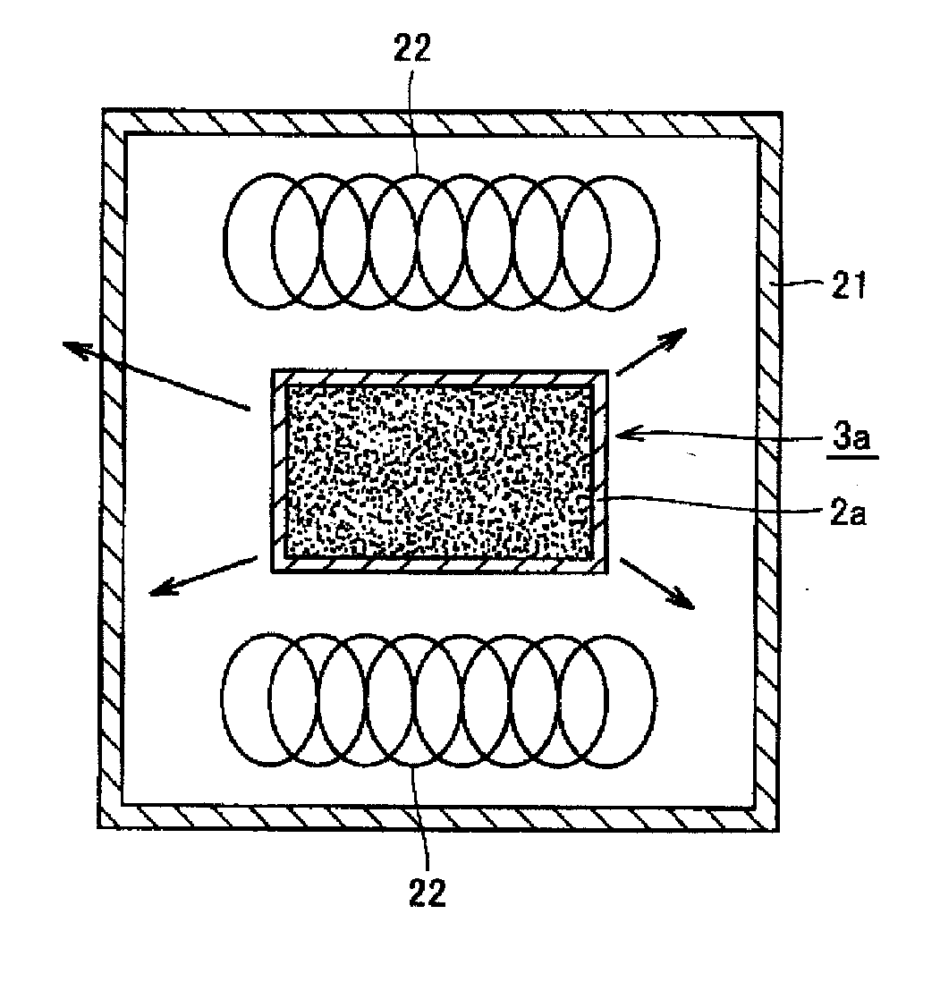
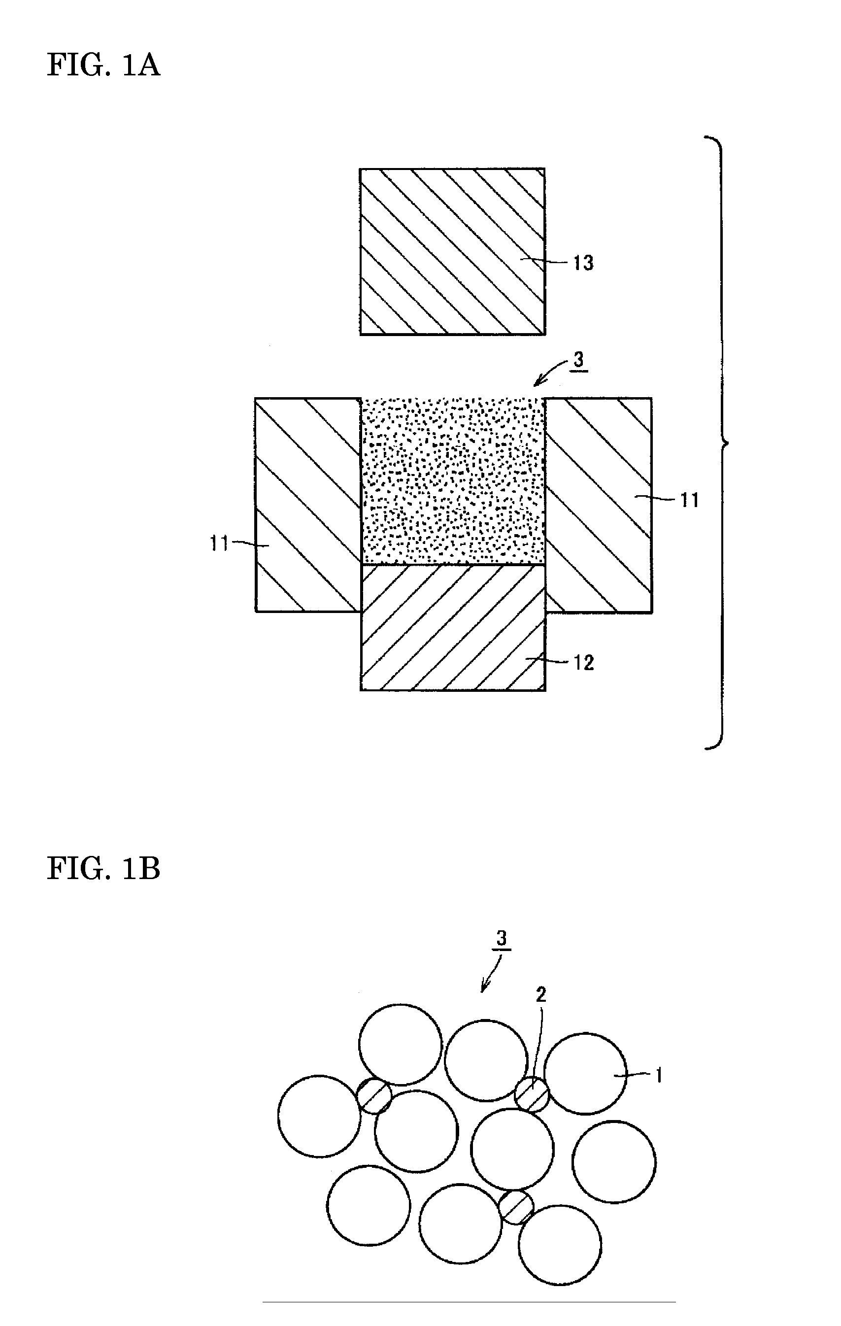
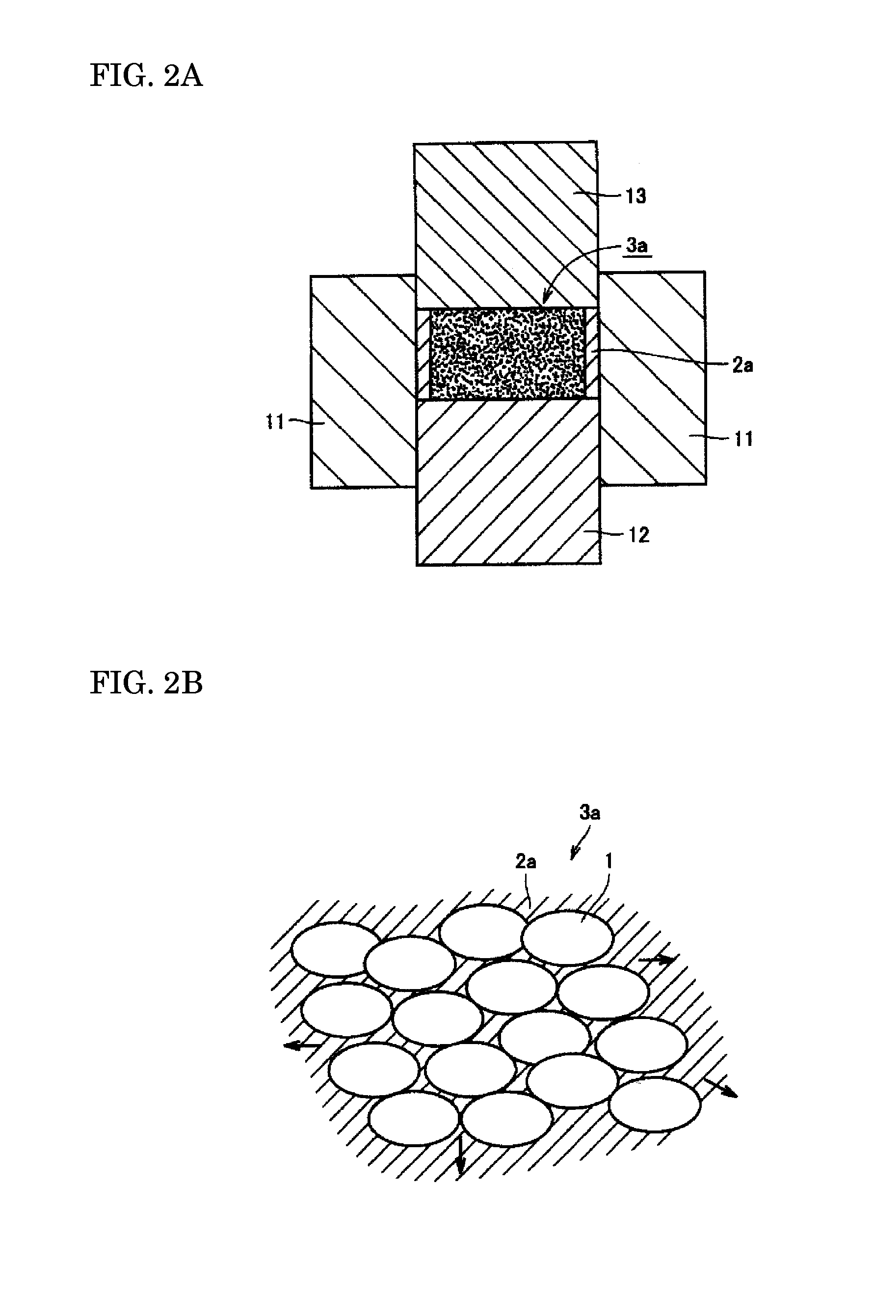
[0010] The present invention provides a method which is effective in reducing the ejecting force by plastic deformation of the resin or wax and reducing the dynamic friction, which is required to improve the surface properties.
[0036] As explained above, sintered parts with complex shapes, good surface properties, and high densities can be molded easily by using the method for molding powder in powder metallurgy and the method for producing sintered parts of the present invention.

Problems solved by technology

However, when amide lubricants are used, as in the publications mentioned above, since the bonding of the amide bond is strong, there are the problems, if the mold temperature is comparatively low, that the lubricant is not caused to bleed out sufficiently between the molded article and the mold and the surface properties of the molded article cannot be made good enough.

Method used


Image

  • Method for Molding Powder in Powder Metallurgy and Method for Producing Sintered Parts
  • Method for Molding Powder in Powder Metallurgy and Method for Producing Sintered Parts
  • Method for Molding Powder in Powder Metallurgy and Method for Producing Sintered Parts

Examples


working example 1

[0062] The kinds of waxes shown in FIG. 1 were prepared and 0.2 wt % of each one was added to iron powder ASC100.29 (Höganäs Co.). Mixing was performed for 1 hour with a V-type mixer and the raw material (mixed powder) was prepared.

TABLE 1123456789KindEsterEsterEsterEsterEsterEsterAmidePar-Stear-affinicacidMelt-41506595110125786560ingpoint(° C.)

[0063] Using the prepared powder, press-molding was performed with a 30 mm diameter cylindrical mold. The mold temperature was 120° C. and the molding pressure was 800 MPa. The surface state of the molded article and the state of the bleeding of the wax were evaluated, and the results are shown in Table 2. In the tables of this Specification, extremely good results are shown by S, good results by Z, somewhat bad results by Y, and bad results by X.

TABLE 2Moldtemperature123456789RoomSurfaceSSSYXXYYXtemperaturestateBleedingSSZYXXXYYing 85° C.SurfaceSSSYXXYYXstateBleedingSSSYXXYYY110° C.SurfaceSSSSXXYZYstateBleedingSSSSXXYYY185° C.SurfaceSSSS...

working example 2

[0067] The types of waxes shown in Tables 4 and 5 were prepared and 0.2 wt % of each one was added to iron powder ASC100.29 (Höganäs Co.). Mixing was performed for 1 hour with a V-type mixer and the raw material (mixed powder) was prepared.

TABLE 4ABCDMelting point85858585Acid value (mg KOH / g)0.60.61.41.4Hydroxyl group value3.04.73.04.7(mg KOH / g)

[0068]

TABLE 5EFGHMelting point41414141Acid value (mg KOH / g)0.60.61.41.4Hydroxyl group value3.04.73.04.7(mg KOH / g)

[0069] Using the prepared powder, press-molding was performed with a 30 mm diameter cylindrical mold. When the raw materials with Samples A, B, C, and D added were used, the mold temperature was 120° C.; when the raw materials with Samples E, F, G, and H added were used, the mold temperature was set at room temperature. The press-molding was performed at a molding pressure of 800 MPa. The surface state of the molded article and the state of the bleeding of the wax were evaluated, and the results are shown in Table 6.

TABLE 6Mold...

working example 3

[0071] Ethylene bisstearic acid amide and zinc stearate were further added in the cases in which 0.2 wt % of the ester waxes of Samples 2 and 4 of Working Example 1 were added. The molding was evaluated under the same conditions as in Working Example 1 and the results are shown in Table 7.

TABLE 7MoldEthylene bisstearic acidtemperatureamideZinc stearateWax(° C.)0.030.20.350.50.030.20.350.52RoomSurfaceSSSSSSSStemperaturestateBleedingSSSSSSSSDensity7.507.467.427.327.527.487.447.35(g / cm3)4150SurfaceSSSSSSSSstateBleedingSSSSSSSSDensity7.537.487.447.367.567.507.467.40(g / cm3)

[0072] Compared with Working Example 1, the surface states were better, and further improvement in the surface state is expected if other non-melting waxes are added. This is thought to be because the static frictional force can be reduced by adding solid lubricants. Since the density is caused to be reduced by adding other waxes, the quantity added is determined by considering the balance between the lubricating pro...


PUM

PropertyMeasurementUnit
Temperatureaaaaaaaaaa

Abstract

A mixed powder is obtained by adding at least one kind of solid ester wax to an iron-based powder for powder metallurgy use. The mixed powder is molded. The melting point of the ester wax is 100° C. or lower, the quantity of the ester wax added is in the range of 0.02 wt % or more to 0.6 wt % or less, and the temperature of the mold when the molding is performed is set in a range of (the melting point of the ester wax+10° C.) or more to 200° C. or less. The ester wax thereby liquefies on the surface of the mold and bleeds out when the molding is performed. As a result, molded sintered parts with complex shapes, good surface characteristics, and high densities can be easily obtained.

Description

CROSS-REFERENCE TO PRIOR APPLICATIONS [0001] This application is a U.S. national phase application under 35 U.S.C. §371 of International Patent Application No. PCT / JP2005 / 015874, filed Aug. 31, 2005, and claims the benefit of Japanese Application No. 2004-257464, filed Sep. 3, 2004, both of which are incorporated by reference herein. The International Application was published in Japanese on Mar. 9, 2006 as International Publication No. WO 2006 / 025432 A1 under PCT Article 21(2).FIELD OF THE INVENTION [0002] The present invention concerns a method for molding powder in powder metallurgy and a method for producing sintered parts. More specifically, it concerns an improved method for lubricating during molding in the field of powder metallurgy, by which it is made easy to obtain molded sintered parts which have complex shapes, good surface characteristics, and high densities. BACKGROUND OF THE INVENTION [0003] In the process of compacting a metal powder in a mold, a large molding press...

Claims


Application Information

Patent Timeline
IPC IPC(8): B22F1/00B22F1/10
CPCB22F1/0059B22F2003/026B22F2998/10C22C33/02B22F2003/145B22F3/10B22F1/10
Inventor TOKUOKA, TERUKAZUHIROSE, KAZUHIRONISHIOKA, TAKAOHANADA, MASAZUMISAWADA, KOUHEI
Owner SUMITOMO ELECTRIC IND LTD
Learn More