
Q-chip MEMS magnetic device

Inactive Publication Date: 2007-10-18
FITBIT INC
View PDF21 Cites 280 Cited by
  • Summary
  • Abstract
  • Description
  • Claims
  • Application Information

AI Technical Summary

Benefits of technology

[0012]An advantage of the present invention is that a payment card is provided that is compatible with existing legacy payment card systems and infrastructure.
[0013]A further advantage of the present invention is that a payment card is provided that has a long service life.
[0014]A still further advantage of the present invention is that a magnetic device is provided that once embedded can blend its magnetic data with permanent recordings in a magnetic stripe.
[0015]Another advantage of the present invention is a payment card is provided that can dynamically generate a new account number each it is used, and by doing so, immediately authenticate itself to the transaction infrastructure.
[0016]Another advantage of the present invention is that a payment card is provided that is far more difficult to copy or skim compared to conventional magnetic stripe cards.
[0017]A further advantage is a magnetic device is provided that can maintain its magnetic data after updating without using battery power.

Problems solved by technology

Track-3 was used by ATM machines for withdrawal limits or history, and is still included for future definition and use, but it still as yet has not found any standardized widespread use.
The problem that developed with conventional credit cards was that the data recorded on the magnetic stripe could be easily duplicated or “skimmed” off the card.
Implementing the electronics that can change all or parts of the magnetic recording on the magnetic stripe of a credit card is difficult and challenging.
The prior art has not recognized that maintaining the magnetic data writing currents for more than a very brief period per use will drain the on-board batteries too quickly.
Conventional devices and methods have not appreciated the problems in aligning the data bits from the encoder properly with the statically recorded bits in the rest of the magnetic stripe.
Prior art devices do not address the changes in field amplitude matches that can occur with different card swiping speeds.
They further have not provided or suggested solutions for the magnetic and mechanical discontinuities that can occur when a thin-film circuit is embedded in a magnetic stripe.

Method used


Image

  • Q-chip MEMS magnetic device
  • Q-chip MEMS magnetic device
  • Q-chip MEMS magnetic device

Examples


Embodiment Construction

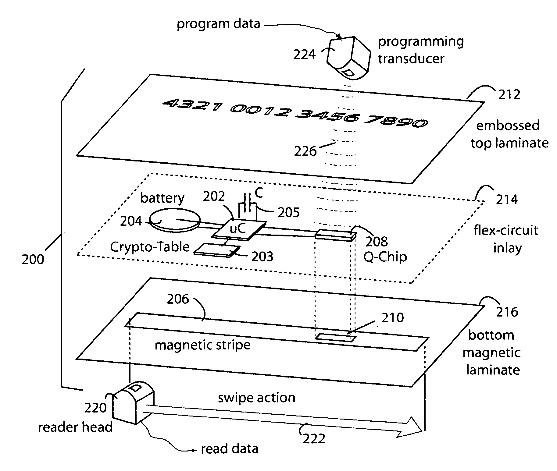
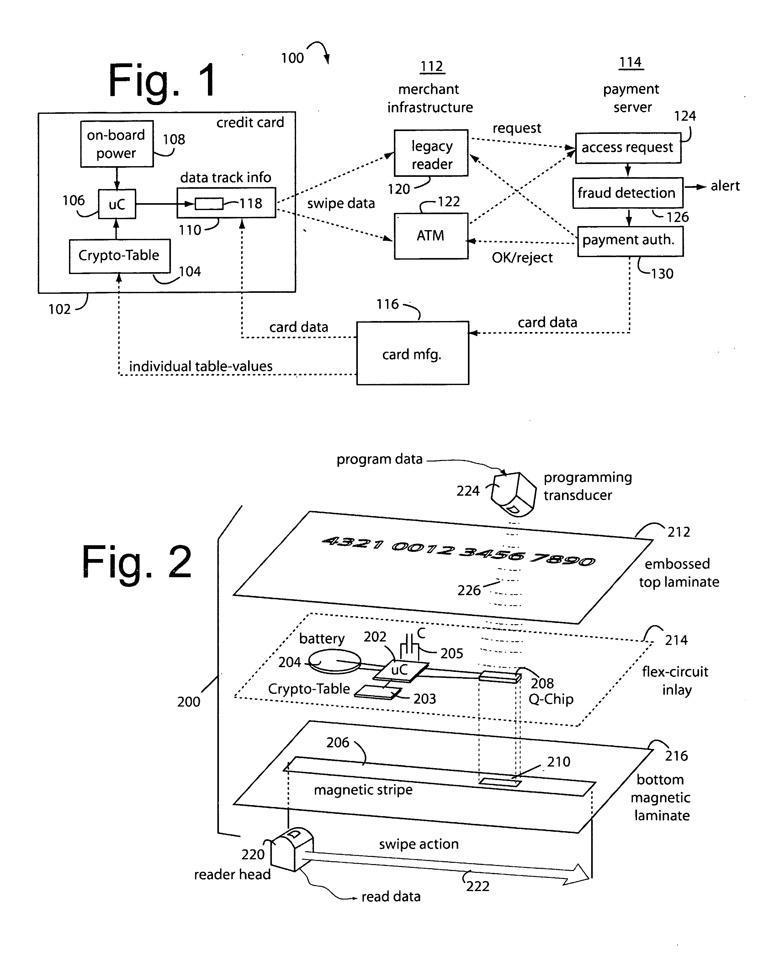
[0031]FIG. 1 illustrates a QSECURE™ payment card system embodiment of the present invention, and is referred to herein by the general reference numeral 100. System 100 greatly reduces the risks of fraud by credit card skimming or data mining from merchant cached data, and yet remains compatible with the vast installed base of magnetic payment card readers in the world.

[0032]The various embodiments possible all share a common core set of technologies. Every basic embodiment includes a card 102 in a credit-card format, a crypto-table or run-time cryptographic algorithm 104, a microcontroller 106 to access the crypto-table or run the cryptographic algorithm, an on-board power source 108, a data track 110 that is partially affected by the microcontroller according to crypto-table or locally derived values, a reader means 112 to communicate the data track information to a payment server 114, and a host server 114 to authenticate the data track information. The dimensions, materials, magn...


PUM


Abstract

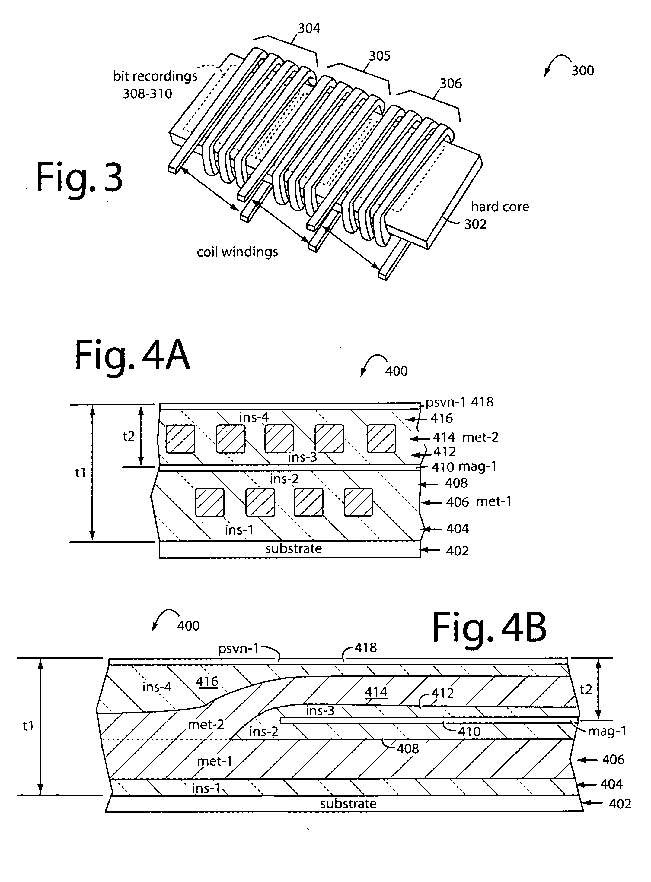
A Q-Chip MEMS magnetic device comprises a thin-film electronic circuit for implantation in the Track-2 area of a magnetic stripe on the back of a credit card. The Q-Chip MEMS magnetic device periodically self-generates new sub-sets of magnetic data that are to be read in combination with other magnetic data that is permanently recorded in the surrounding surface of the magnetic stripe. A collocated battery and microcontroller provide operating power and new data for magnetic bit updates. A swipe sensor triggers such updates by sensing electrical contact with a legacy card reader. Several thin-film coils of wire are wound end-to-end around a common, flat, ferrous core. These are driven by the microcontroller. In one instance, such core comprises “hard” magnetic material with a coercivity of 200-300 Oersteds. Magnetic data written from the corresponding adjacent coils will persist for later readings by a legacy card reader. In another instance, the core comprises “soft” magnetic material with a coercivity of about one Oersted. A media stripe of “hard” magnetic film material overlays respective coils to receive magnetic data transfers. Magnetic data written from the corresponding adjacent coils will persist in the overlaying hard media for later readings by a legacy card reader. In a data input mode, the thin-film coils can be used as readers to provide updates and new programming to the microcontroller.

Description

RELATED APPLICATIONS[0001]This Application is a continuation-in-part of U.S. patent application Ser. No. 11 / 404,660, filed Apr. 14, 2006, by two of the present inventors, Kerry D. BROWN and David K. PARISEAU, and titled AUTOMATED PAYMENT CARD FRAUD DETECTION AND LOCATION. Such patent application was, in turn, a continuation-in-part of now issued U.S. Pat. No. 7,044,394 B2, issued May 16, 2006, and both documents are incorporated herein by reference.BACKGROUND OF THE INVENTION[0002]1. Field of the Invention[0003]The present invention relates to magnetic data recording devices, and more particularly to thin-film micro electromechanical system (MEMS) electronic devices placed in magnetic stripes that provide for a dynamic part of an otherwise static data recording.[0004]2. Description of Related Art[0005]Magnetic data recordings have been an important medium for use in video, audio, and computer data storage. Tapes have been configured on reels, cassettes, and cartridges. Short segment...

Claims


Application Information

Patent Timeline
IPC IPC(8): G06K19/06
CPCG06Q20/26G06Q20/385G07F7/1016G07F7/08G06Q30/00G11B5/00808
Inventor BROWN, KERRY D.PARISEAU, DAVID K.LI, WEIDONGWILLIAMS, EDGAR M.THOMPSON, JOYCE
Owner FITBIT INC
Learn More