
Spring-Assisted Mechanism for Raising and Lowering a Load

a technology of a spring and a load, which is applied in the direction of instruments, wing accessories, entry/exit registers, etc., can solve the problems of infiltration of cold air and rain, motors can be relatively large and expensive, electronics could be damaged, etc., and achieve the effect of greatly enhancing the ability of non-technical home owners to troubleshoot and repair devices

Inactive Publication Date: 2007-10-11
AMBROSE JOSEPH V
View PDF55 Cites 54 Cited by
  • Summary
  • Abstract
  • Description
  • Claims
  • Application Information

AI Technical Summary

Benefits of technology

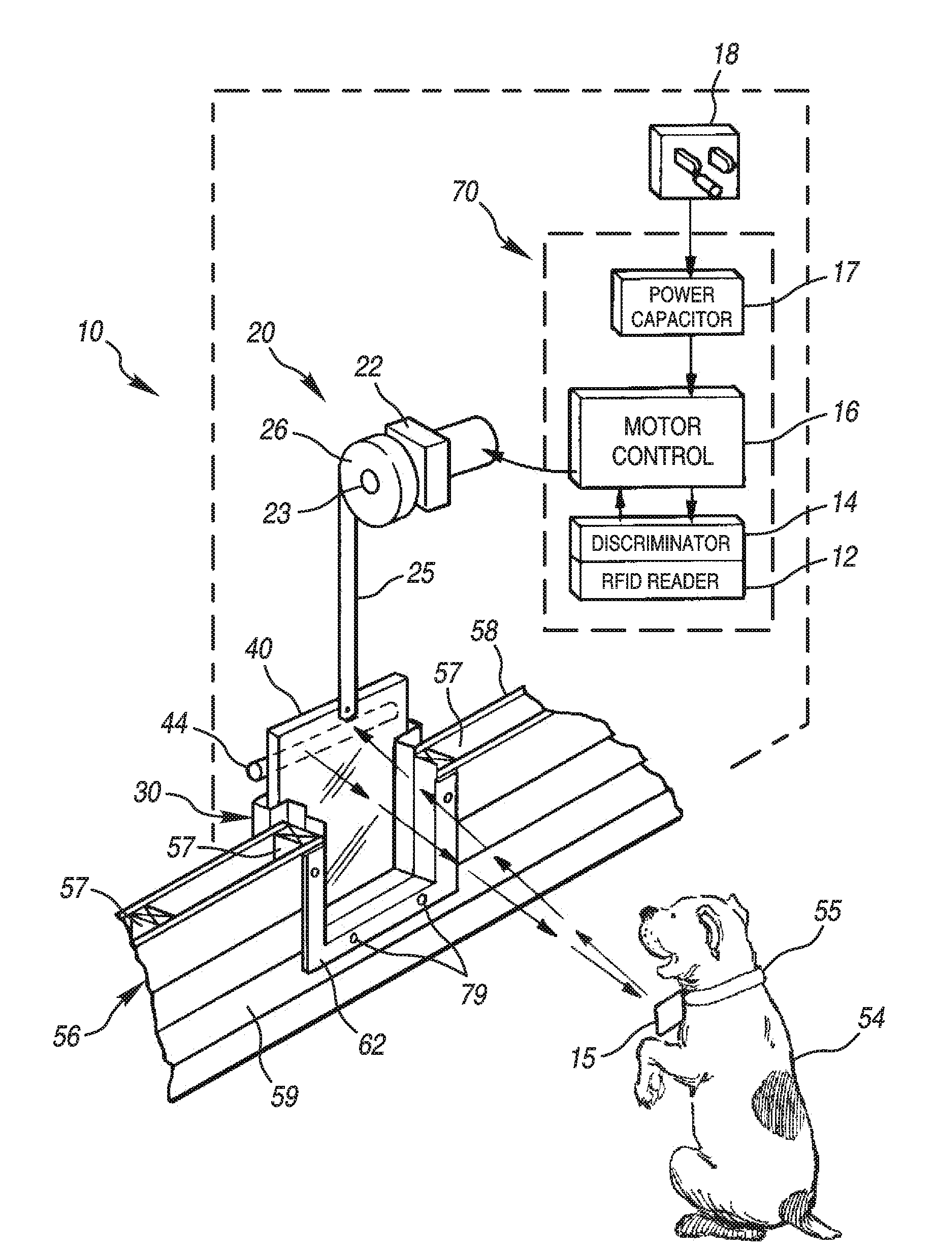
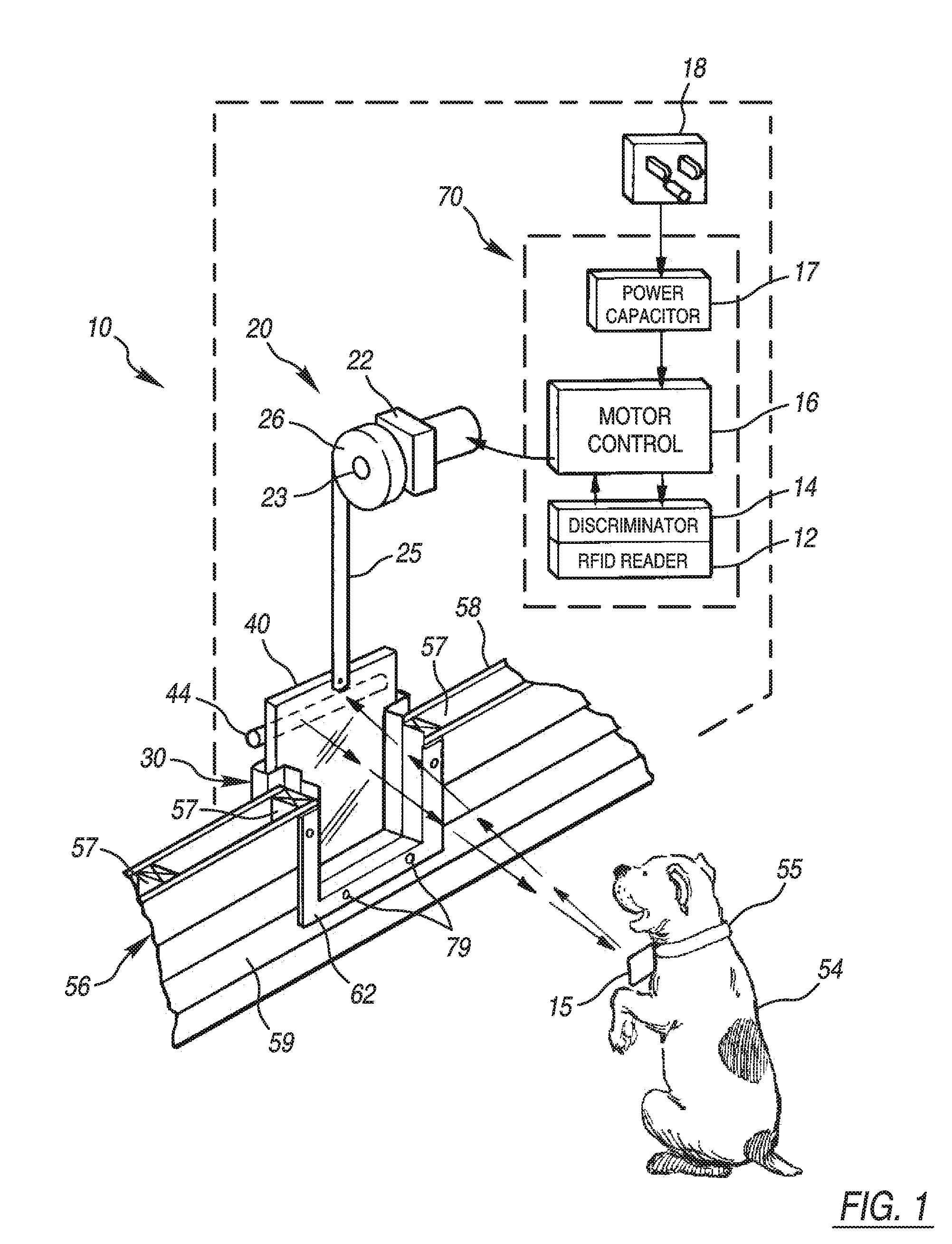
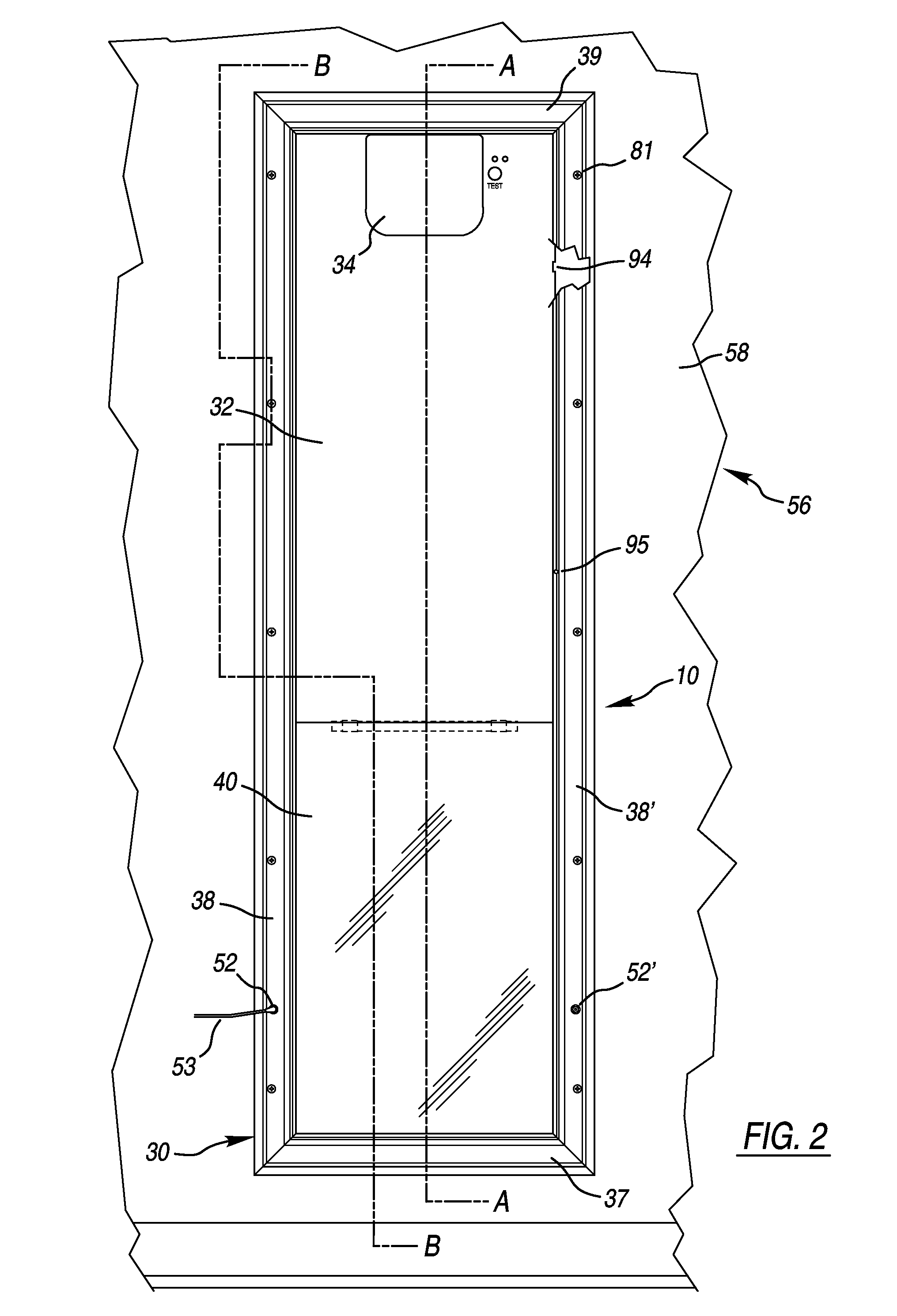
[0011]Still another embodiment of the present invention includes a programmable pet door system that provides a vertically rising door that may be sealed against the elements by low friction, fibrous seals on one or more of its edges which may also serve to guide the door's panel through its motion. The panel may be raised by a gear motor which may have a constant tension spring mounted on its output shaft. An extended end of the constant tension spring may engage a lever which may be mounted on the upper end of the panel. The upper end of the panel may also contain a spring loaded latch that may engage an opening in a frame of the device to securely lock the panel in the generally closed position. The latch may be withdrawn from engagement by a link between it and the lever in a manner such that the latch may be fully withdrawn before the additional pull on the constant tension spring causes the panel to move upward. The frame may be configured to maintain the movable panel, its seal strips, the gear motor, the control panel, the latching means and the constant tension spring all inside the plane of the inner wall of the enclosure that the pet door serves. This configuration may be further optimized by confining all the large, horizontally thick members of the mechanism such as the gear motor and its mounted constant tension spring centrally located at the top of the structure which may enable a relatively compact cover to contain and conceal them and removably attach to a thin cover panel that may conceal the balance of controls and mechanism above the opening for the pet. This embodiment can result in an attractive, relatively thin housing on the inside of the wall or door and a small opening through the wall or door that is slightly larger than the net opening of the pet door.
[0012]In one embodiment, the seals strips may engage the entire perimeter of the outward face, the sides and bottom of the inward face and both vertical edges and the bottom edge of the door panel. In one embodiment, the cover panel may be made of a relatively thin, but of a stiff and strong material with edges confined in a channel spaced inwardly from the door panel. The cover panel may be fastened in place in the normal, uppermost location with its lower edge above the uppermost opening for the pet to pass through. The cover panel may be unfastened and lowered for access to the mechanism and controls or may be fastened in the fully down location to provide additional security to supplement the latched door panel during periods of prolonged disuse such as during a vacation or for hurricane protection.
[0013]While this pet door fully contemplates the use of an AC gear motor, in one embodiment, a low voltage DC gear motor may be used which may be supplied by a remote, plug-in power supply having an output current that may be purposely below the full power requirement of the gear motor. The control circuit may provide one or more capacitors which are fully charged by the power supply between opening cycles. Upon the gear motor being energized by the control, it may be fully powered by both the discharge of the capacitor and the power supply and aided by the constant tension spring, it vigorously unlatches and begins pulling the door panel upward. The capacitor may be sized so that it may be exhausted before the panel reaches the fully open position, such that the output of the undersized power supply alone drives the panel its final distance. This reduced power level may be little more than enough to maintain the panel in the full open position. When the dwell period, which may be adjustable, expires, the power is cut to the gear motor and the weight of the panel overcomes the pull of the constant tension spring and the frictional resistance of the sealing strips. This causes the panel to slowly descend against the bias of the spring, back winding the gear motor and eventually bottoming out with a net force of a few ounces which is less than what might cause injury or for that matter even pain to a lingering pet. This configuration therefore advantageously eliminates the need for sensors or other protective devices to prevent pinching when the load bottoms out. The use of the capacitor that is fully charged shortly after each operating cycle may provide an important additional benefit. RFID electronics require a D.C. power supply with a relatively low ripple. Another embodiment may eliminate the use of power capacitors and utilize a power supply of adequate capacity to fully power the motor in the upward direction and in a manner that is disclosed below, powering it in a down direction with a reduced voltage. So configured, the system may include a programmable micro-processor and one or more switches such as reed switches for detecting when the panel reaches a full open position, for example.
[0014]The use of a DC gear motor allows the use of a dynamic braking resistor across its leads to supplement the drag of the sealing strips and the gear train when the power is cut to the gear motor and the panel is descending. The amount of resistance may be adjustable which would create the opportunity to compensate for the change in frictional resistance of the sealing strips due to long term wear or the effects of severe changes in weather.
[0018]In at least one embodiment, the ability for the non-technical home owner to troubleshoot and repair the device may be greatly enhanced. A manual press to operate switch may be provided to determine if a failure to operate is due to the pet detection control or the power and gear motor portion. The cover protecting and concealing the large protruding components may be a snap fit for quick and easy removal which could expose at least a single fastener which if removed, would allow the cover panel to be lowered exposing all of the controls and mechanism. The sliding door and the sliding cover panel, which can be located inside the plane of the surface of the inside wall or door, may be removed and replaced by merely removing the top cap of the device's frame.

Problems solved by technology

Depending on the size and weight of the article requiring lifting, the motor can tend to be relatively large and expensive.
However, in keeping the closing force down to where a dog's face could overcome it, a relatively mild wind could cause infiltration of cold air and rain.
In addition, the electronics could be damaged by dangling into a water dish while a pet takes a drink.
While the Solowiej panel rides within channels in side walls, Solowiej provides nothing to resist the infiltration of wind and moisture.
Further, the Solowiej device is bulky and thick.
While the opening in the outer wall of the home is acceptably not much bigger than the door opening for the pet, the very large, full height cavity required to mount it between the studs may be acceptable in a wall, but it would be difficult to hang on a door.
A further shortcoming of the commercialized version of this device is the fact that placed between the existing standard spaced studs of a wall, its vertical side walls restrict the width of the available opening such that the maximum size dog would be about 90 pounds in weight.
With a 120 volt AC line voltage power cord coming out of its bottom, it is a potentially dangerous thing on a swinging door, particularly so if the cord exits on the side furthest from the door's hinges.
The problem is that with greater range, the pet door will be actuated repeatedly every time the pet passes or remains within range of the transmitter which can be a few yards or more.

Method used


Image

  • Spring-Assisted Mechanism for Raising and Lowering a Load
  • Spring-Assisted Mechanism for Raising and Lowering a Load
  • Spring-Assisted Mechanism for Raising and Lowering a Load

Examples


Embodiment Construction

[0045]For the purpose of promoting an understanding of the principles of this invention, reference will now be made to the embodiments illustrated in the drawings and specific language will be used to describe the same. It will be nevertheless understood that no limitation of the scope of the disclosure is thereby intended. The disclosure includes any alterations and further modifications in the illustrated devices and described methods and further applications of the principles of the disclosure that would normally occur to one skilled in the art to which this disclosure relates.

[0046]The present disclosure describes a spring-assisted mechanism for raising and lowering a load. The disclosed embodiment includes a pet door. However, the device may similarly be incorporated into other systems such as, for example, point-of-purchase advertising components or any other system requiring such a mechanism. The pet door of the disclosed example may easily be installed in the door or wall of...


PUM


Abstract

An apparatus for selectively raising, lowering or otherwise moving load such or panel, or other article such as a pet door comprises a frame, a panel, a motor, a constant tension spring, and a control system. The panel is carried by the frame for movement between an open position and a closed position. The spring is attached to the panel to bias the panel open. The frame includes a plurality of groves retaining seals such as fibrous weatherseal to seal the interface between the panel and the frame against penetration by the elements. The control system is in communication with the motor to actuate the motor, thereby moving the panel with the assistance of the spring. The control system includes an antenna in the panel for emitting a low frequency (RFID) signal, and a fob that is worn by a pet to communicate with the antenna to actuate the motor.

Description

CROSS-REFERENCE TO RELATED APPLICATIONS[0001]The present application is based on and claims the benefit of priority of U.S. Provisional Patent Application No. 60 / 790,880, filed Apr. 11, 2006, the entire contents of which are hereby expressly incorporated herein by reference.BACKGROUND OF THE INVENTION[0002]Currently, various systems are available for providing powered opening and closing of doors such as pet doors, and raising, lowering or otherwise moving loads or articles in point-of-purchase displays and the like, or even for raising and lowering loads or articles such as projector screens, chalkboards, dumb-waiter doors, plasma and LCD televisions, for example. Typically, these systems include a motor and a pulley assembly. Depending on the size and weight of the article requiring lifting, the motor can tend to be relatively large and expensive.[0003]One example of a market wherein various alternative solutions to opening and closing doors, for example, exist, is the pet door in...

Claims


Application Information

Patent Timeline
IPC IPC(8): E05D15/48
CPCE05D13/1276E05D13/1284E05Y2400/302E05Y2900/106E05F15/76G07C9/00309E05Y2800/71E05Y2800/00E05F15/665E06B7/32
Inventor SIEGAL, BURTON L.AMBROSE, JOSEPH V.
Owner AMBROSE JOSEPH V
Learn More