Temperature fuse and battery using the same

Inactive Publication Date: 2007-09-13
PANASONIC CORP
View PDF3 Cites 3 Cited by
  • Summary
  • Abstract
  • Description
  • Claims
  • Application Information

AI Technical Summary

Benefits of technology

[0006] The thermal fuse has the volume of the space in the insulating case between the fusible alloy and the sealer is larger than the volume of the flux provided on the fusible alloy. Therefore, when the flux melts according to an increase of an ambient temperature, most of the flux moves into the space in the insulating case between the fusible alloy and the sealer. The amount of the flux existing on the fusible alloy is accordingly very little. Therefore, even when arc is generated between tips of the melting fusible alloy according to a further increase of the ambient temperature to exceed the melting point of the fusible alloy, the amount of flux vaporized due to the arc can be reduced. This suppresses a pressure rise of the space in the thermal fuse, thus preventing the sealing from deteriorating and preventing the insulating case in the thermal fuse from a damage even when the fuse is used at a high voltage or a large current.

Problems solved by technology

If the energy of the arc is large, the energy may cause the sealing to deteriorate or damages the insulating case 1 of the thermal fuse.
Therefore, the conventional thermal fuse cannot be used as a thermal fuse for breaking a high voltage or a large current.

Method used


Image

  • Temperature fuse and battery using the same
  • Temperature fuse and battery using the same
  • Temperature fuse and battery using the same

Examples


exemplary embodiment 1

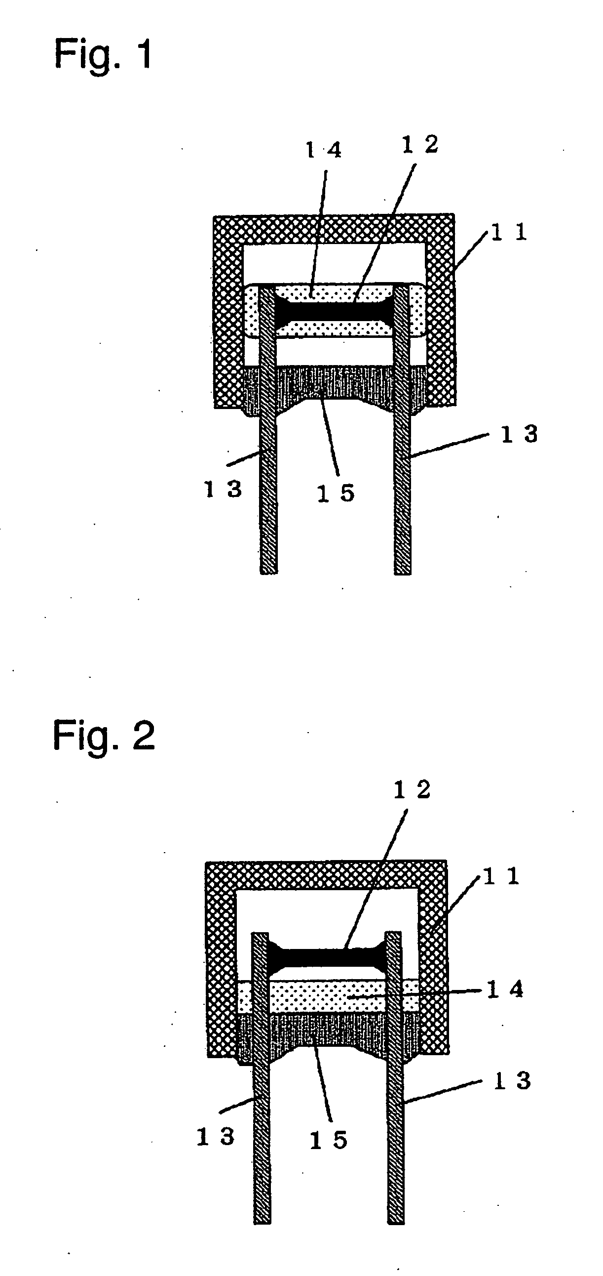
[0039]FIG. 1 is a sectional view of a radial-type thermal fuse according to Exemplary Embodiment 1 of the present invention. FIG. 2 is a sectional view of the thermal fuse having melting flux. A cylindrical or rectangular insulating case 11 having a bottom and having an opening provided therein is made of one of polybutylene telephthalate (PBT), polyphenylene sulfide (PPS), polyethylene telephthalate (PET), phenol resin, ceramic, and glass. Fusible alloy 12 having substantially a cylindrical or rectangular shape is provided in the insulating case 11. The fusible alloy 12 is made of one of tin, lead, zinc, bismuth, indium, cadmium, silver, copper, and alloy of these metals. Respective ends of a pair of lead conductors 13 are connected to respective ends of the fusible alloy 12. Respective other ends of the lead conductors 13 are led out of the insulating case 11 through the opening of the insulating case 11. The lead conductors 13 having a wire shape may be made of single metal, such...

exemplary embodiment 2

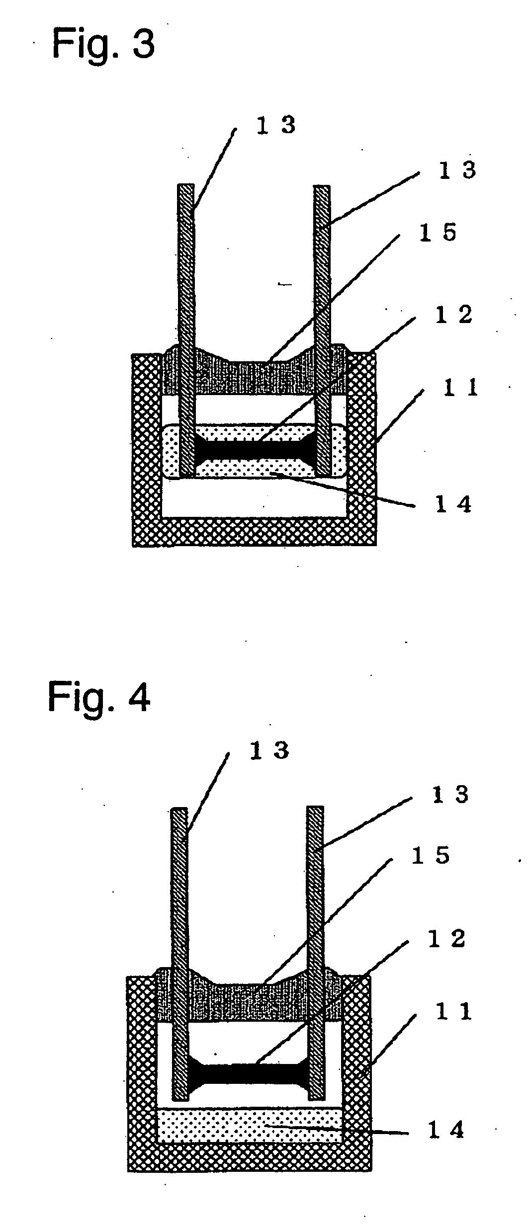
[0042]FIG. 3 is a sectional view of a radial-type thermal fuse according to exemplary Embodiment 2 of the present invention. FIG. 4 is a sectional view of the thermal fuse having melting flux. The thermal fuse of Embodiment 2 includes the same components as those of a thermal fuse of Embodiment 1 shown in FIGS. 1 and 2. The fuse of embodiment 2, differently from that of Embodiment 1, the volume of a space in an insulating case 11 between a fusible alloy 12 and a bottom of an insulating case 11 is larger than the volume of flux 14, as shown in FIG. 3 Upon being used on an electronic device or a heating component, such as a transformer or a motor, as shown in FIG. 4, the radial-type thermal fuse of Embodiment 2 is attached to the electronic device or the heating component, so that the space between the fusible alloy 12 and the bottom of the insulating case 11 is positioned substantially in the same direction as the gravity from the fusible alloy 12. According to Embodiment 2, the volu...

exemplary embodiment 3

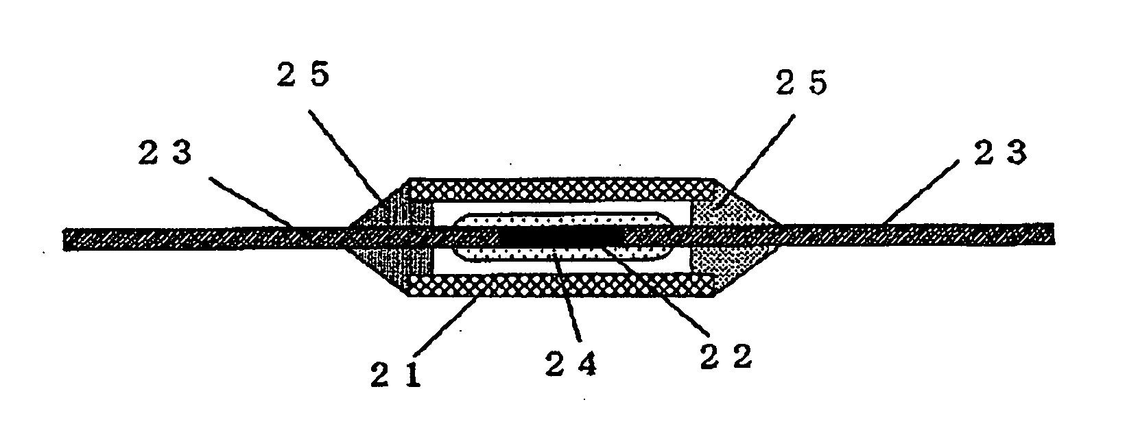
[0043]FIG. 5 is a sectional view of an axial-type thermal fuse according to Exemplary Embodiment 3 of the present invention. FIG. 6 is a sectional view of the thermal fuse having melting flux. An insulating case 21 having a cylindrical or rectangular shape and having openings provided therein is made of one of polybutylene telephthalate (PBT), polyphenylene sulfide (PPS), polyethylene telephthalate (PET), phenol resin, ceramic, and glass. Fusible alloy 22 having substantially a cylindrical or rectangular shape is provided in the insulating case 21. The fusible alloy 22 is made of one of tin, lead, zinc, bismuth, indium, cadmium, silver, copper, and alloy of these metals. Respective one ends of a pair of lead conductors 23 are connected to respective ends of the fusible alloy 22. Respective other ends of the lead conductors 23 are led out of the insulating case 21 through the opening of the insulating case 21. The lead conductors 23 having a wire shape is made of single metal, such a...


PUM


Abstract

A thermal fuse includes an insulating case having a bottom and having an opening provided therein, a fusible alloy provided in the insulating case, a lead conductor having one end connected to the fusible alloy and other end led out from the insulating case through the opening of the insulating case, a flux provided on the fusible alloy, and a sealer for sealing the opening of the insulating case. The volume of a space between the fusible alloy in the insulating case and the sealer is larger than the volume of the flux. Sealing of the fuse is prevented from deteriorating, and the insulating film is prevented from damage even when the thermal fuse is used for breaking a large current at a high voltage.

Description

[0001] This application is a divisional application of application Ser. No. 10 / 479,577, which is a U.S. National Stage (§371) of International Application PCT / JP02 / 05534, filed Jun. 5, 2002TECHNICAL FIELD [0002] The present invention relates to a thermal fuse and a battery including the fuse. BACKGROUND ART [0003]FIG. 32 is a sectional view of a conventional thermal fuse. The conventional thermal fuse shown in FIG. 32 includes fusible alloy 2 including tin and a pair of lead conductors 3 connected to respective ends of the alloy 2. The connectors may be connected by welding or supersonic welding, or by melting the fusible alloy 2 with an electrical power applied to the lead conductors 3 and the fusible alloy 2. The fusible alloy 2 is coated with flux 14, and accommodated in insulating case 1 having an opening. The opening of the insulating case 4 is sealed with sealer 5 made of hard resin. [0004] In the conventional thermal fuse, the flux 3 melts according to an increase of an ambie...

Claims


Application Information

Patent Timeline
IPC IPC(8): H01M6/00H01H37/76H01M6/50H01M50/574
CPCH01H37/761H01H2037/768H01M2200/103H01M2/348H01M2/34Y02E60/10H01M50/581H01M50/574
Inventor SENDA, KENJIKONO, ATSUSHIWADA, TATSUYA
Owner PANASONIC CORP
Why Eureka
Try Eureka