In particular, non-relevant illumination, e.g., illumination directed at portions of the substrates that do not include signal sources, can give rise to substantial amounts of
optical noise that will reduce the optical signal-to-
noise ratio of the
system, thus driving down the sensitivity of the
system.
Disadvantages of excess illumination also flow through the
system, including providing increased power requirements for the excitation
light source to ensure a
diffuse illumination pattern provides sufficient illumination power in all desired locations.
This leads to increased cost and power dissipation requirements due to the incorporation of lasers with higher powers.
Additionally, excessive illumination can
impact data processing parameters by providing irrelevant data in spaces between relevant signals.
Further, thermal effects, e.g., heating, are a function of the amount of
laser power directed at chemical and biological samples, and can substantially negatively
impact applications of these systems.
However, as will be appreciated, because laser power is limited, and indiscriminate illumination may cause certain adverse effects, e.g., heating,
autofluorescence, and consequently reduced optical signal:
noise ratios (SNR), it may be desirable to avoid illuminating non-signal generating portions of the substrate.
Such reflected activation
radiation gives rise to elevated
noise levels for the system.
In addition, the substrate materials may also autofluoresce in response to illumination, giving rise to additional sources of
optical noise to the system.
Unfortunately, use of multiple different sources may provide issues regarding differences between the individual sources, e.g.,
wavelength, frequency or intensity of illumination that may
impact the signals resulting therefrom, e.g., rendering slightly different signal profiles.
Additionally, such multiple excitation source systems may still give rise to the problems of excessive illumination of the substrate, as a whole.
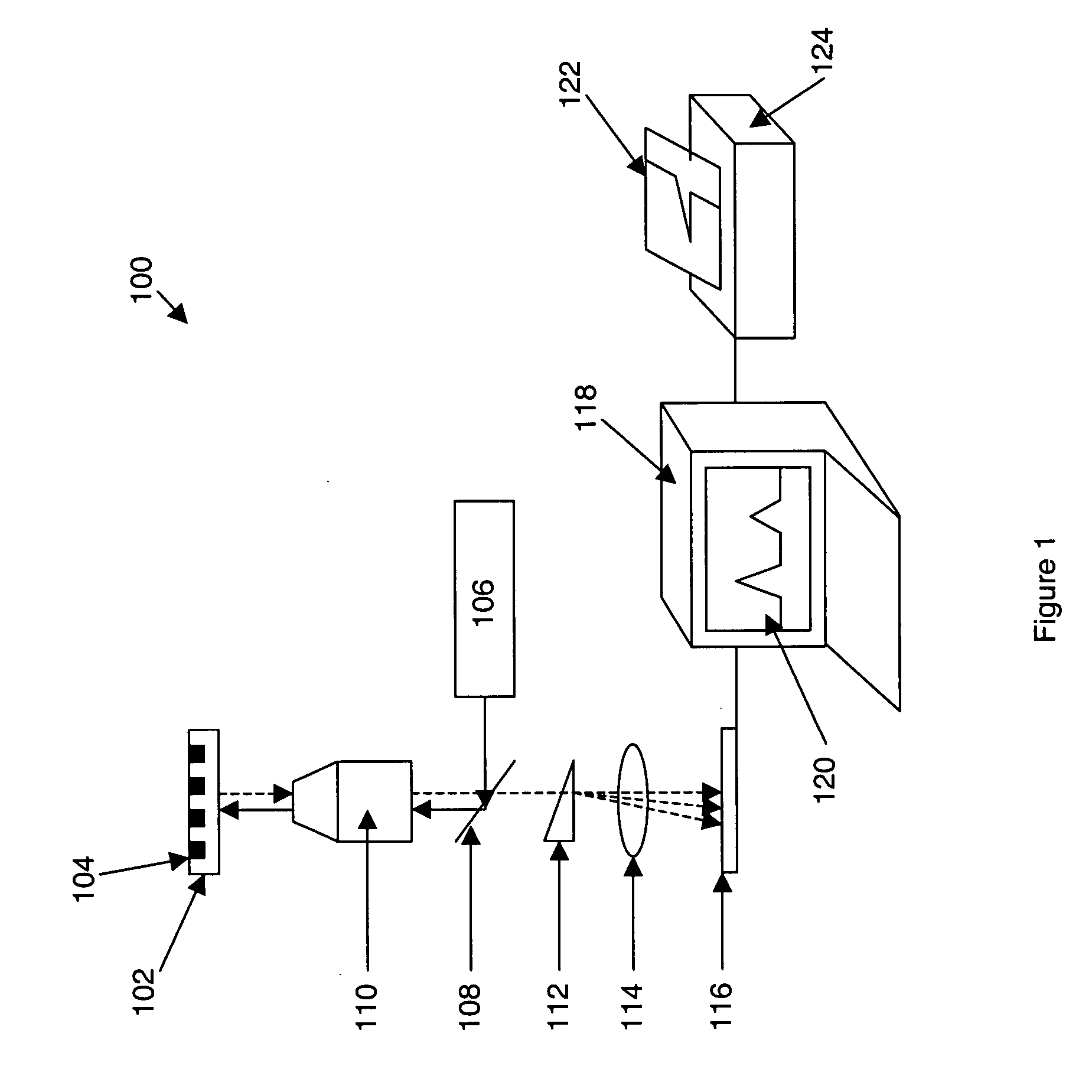
For example, in the case of systems that
direct excitation illumination at the
signal source and measure responsive
fluorescence, such noise can be a result of reflected excitation radiation that bleeds through the fluorescence collection
optics,
autofluorescence of the substrate or other illuminated materials, and the like.
As noted elsewhere herein, such irrelevant illumination yields problems of wasted or otherwise problematic illumination power, and excessive noise levels deriving from, e.g., illumination bleed through, autofluorescence, etc.
In particular, in linearizing an illumination spot, one does not eliminate the decrease in intensity at the spot's edges, but merely refocuses those decreases.
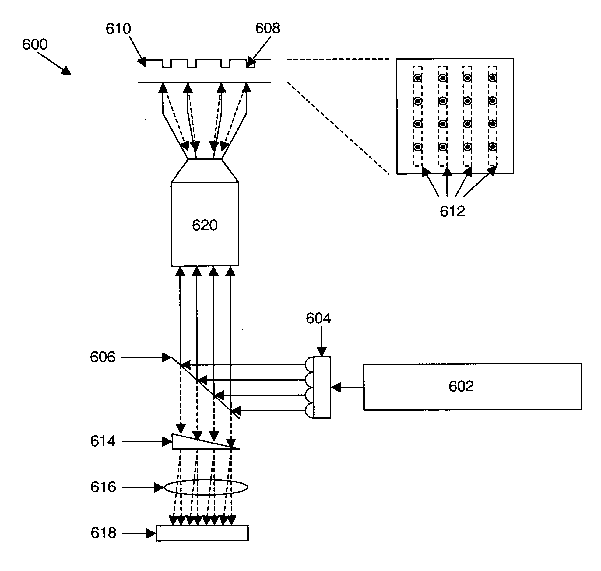
However, due to the costs associated with multiple excitation sources such as lasers, the amount of space required for more complex optical trains, and the like, in many cases it is preferable to divide up illumination beams from one or only a few excitation sources.
While the use of any of the foregoing deflective elements is effective in providing multiple beams, their use can have limited flexibility in some regards.
While effective at providing multiple illumination beams upon a substrate, it will be appreciated that the use of standard
beam splitters and reflective
optics may be difficult to implement for larger scale
multiplexing of the system.
In particular, the reflective
optics required for each separate beam substantially add to the complexity and cost of the optical
train of a system that seeks to provide greater numbers of discrete illumination beams, e.g., 2, 4, 8, 10, 20, 40, 50 or more discrete beams, directed at an individual substrate.
Additionally, because each of the beams will be substantially identical to each other beam, recombination of beams to direct them at closely spaced regions of a substrate, using a single optical element, such as a
beam splitter, will result in substantial losses of applied energy (as only half of the photons from each beam would be directed at the substrate), as shown by arrows 922 and 924 in FIG. 9, above.
Again, however, such deflective elements will generally not provide full control over the deflection of individual beams relative to each other.
While the degree of rejected excitation light attainable in such transmissive fluorescence geometries is sufficient for most one or two excitation band applications, these current schemes may not be effectively extended to three or four excitation band schemes, as a single transmissive-fluorescence filter that efficiently passes substantial portions of multiple, e.g., 2, 3, 4 or more, different
fluorescent spectra while reflecting the multiple excitation bands, is not readily manufacturable using available technology.
Further, while multiple filter components could be combined to achieve this in a multiple laser, multiple emission
wavelength system, increased transmission losses, increased optical aberrations, increased size, and increased costs for making higher performance fluorescence transmissive filter systems, make such solutions less desirable.
As alluded to above, one contributor to the
noise level produced by a fluorescence based optical analysis system is through the generation of autofluorescence in the system's optical components, e.g., the substrates.
While multiple different objectives may be used, such systems may have limitations in their flexibility.
In some cases, two different signals that may be emitted from a given
signal source may not be completely spatially separable onto different regions of a
detector array.
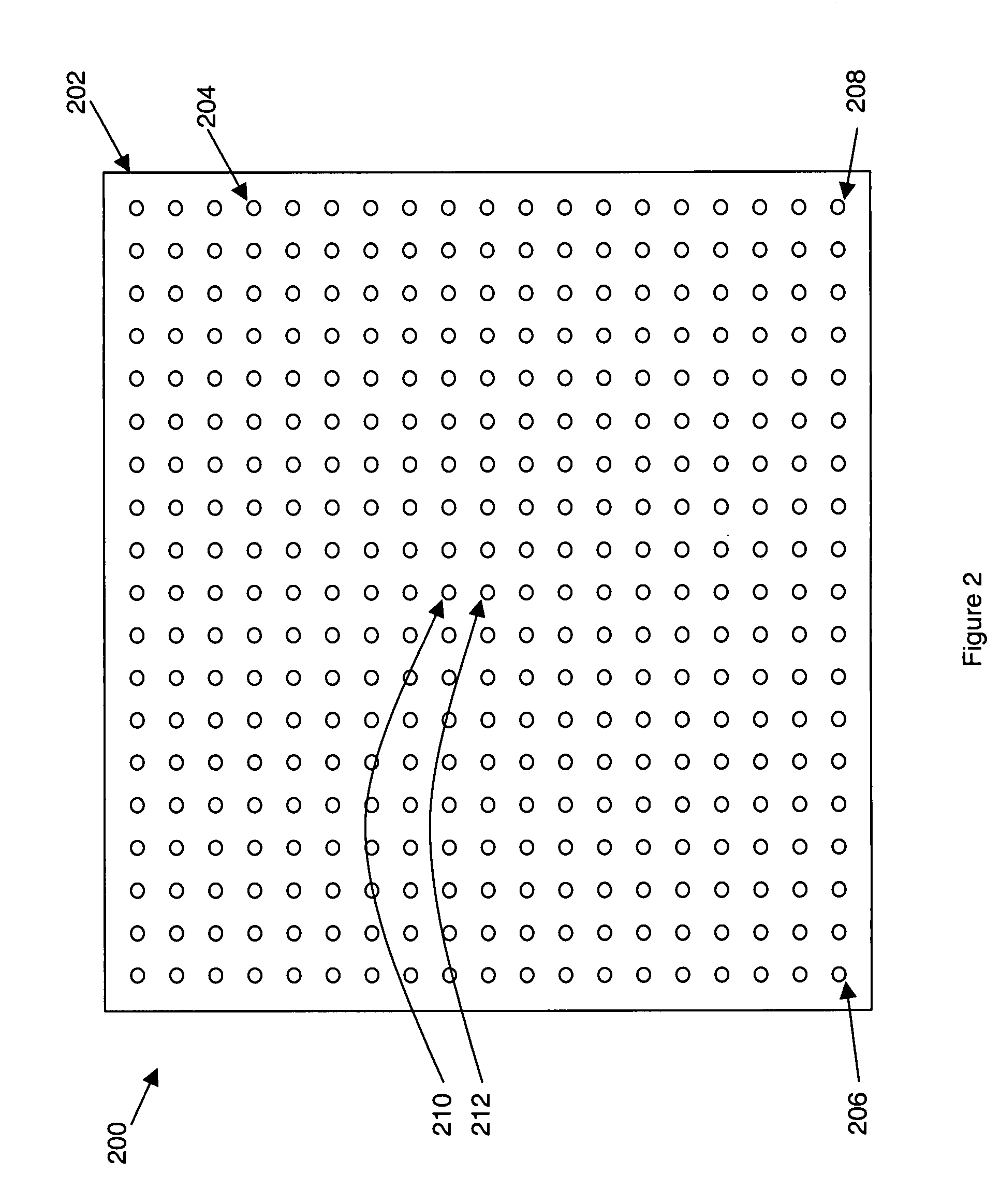
By way of example, where one is imaging a large number of discrete signal sources or separated signals derived from such sources, on a single
detector array, e.g., a CCD, ICCD or EMCCD, space between imaged signals from such discrete sources gives rise to little or no useful data, as it is a “quiet” space.
While such signals can be disregarded as background, their recording and
processing to the point of discard still requires memory space for storage and
processing capacity for evaluation and ultimate discard.
As will be appreciated, because constituent signal wavelengths tend to fall over a range rather than within a precise single
wavelength or
wavelength range in some cases, and because addition of more signal wavelength components within the signal sources as may occur with various applications and / or
multiplexing, spatial separation may yield less than complete separation between different signal constituents along each row, e.g., resulting in spectral overlap of the separated signals.
