Light olefin production via dimethyl ether
a technology of dimethyl ether and light olefins, which is applied in the field of production of light olefins, can solve the problems of general failure to provide processing schemes and arrangements, and achieve the effect of improving processing schemes and arrangements
- Summary
- Abstract
- Description
- Claims
- Application Information
AI Technical Summary
Benefits of technology
Problems solved by technology
Method used
Image
Examples
examples
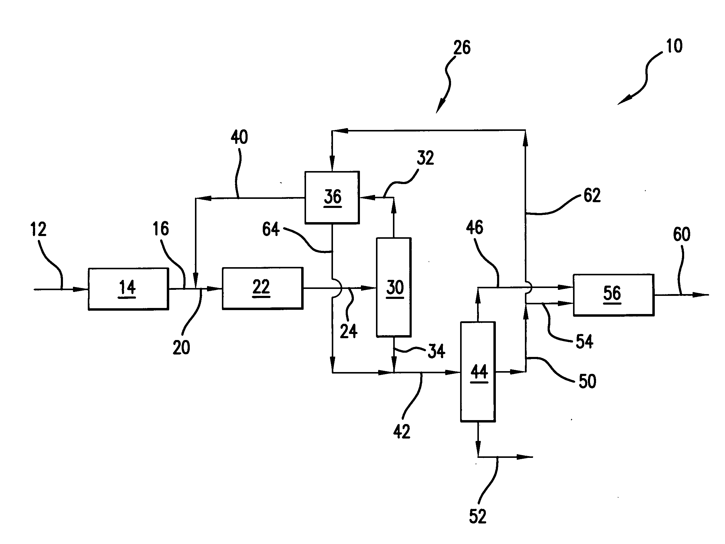
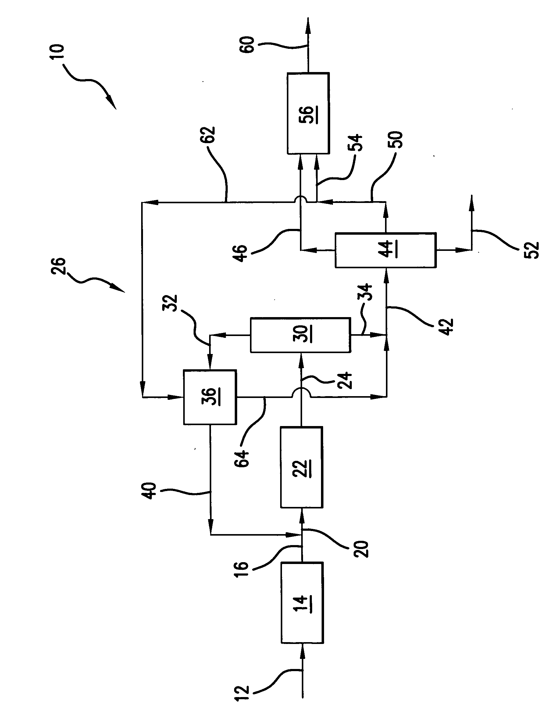
[0039] Those skilled in the art and guided by the teachings herein provided will appreciate that the use of dimethyl ether as a primary or principal oxygenate feedstock
[0040] to such an oxygenate conversion reactor section and, in accordance with certain preferred embodiments, and excluding residual amounts of other materials, as the primary or principal oxygenate feedstock and, in accordance with other certain preferred embodiments and excluding residual amounts of other materials, as the sole oxygenate feedstock, desirably produces or results in various processing advantages.
examples 1
Reactor Size
[0041] Methanol conversion to the light olefins ethylene and propylene at a 1:1weight ratio necessitates the following processing reaction:
24 CH3OH→6C2H4+4 C3H6+24 H2O
In such processing, 24 mols of methanol feed becomes 34 mols of product effluent. The use of dimethyl ether, in accordance with a preferred embodiment, for a similar conversion to the light olefins ethylene and propylene at a 1:1 weight ratio necessitates the following processing reaction:
12 CH3—O—CH3→6 C2H4+4 C3H6+12 H2O
In such processing, 12 mols of dimethyl ether feed becomes 22 mols of product effluent.
[0042] Thus, processing in accordance with the above reaction from dimethyl ether as opposed to reaction from methanol, both for the same number of mols of ethylene and propylene, results in a reduced number of mols of effluent (e.g., 22 mols versus 34 mols). Such reduction in the number of mols represents an equivalent reduction in the volumetric flow rate of effluent from the reactor, and thus a sm...
example 2
Heat of Reaction
[0043] The heat of reaction, at b 450° C., for the oxygenate conversion reaction of two mols of methanol to one mol of ethylene (plus water) is about 5.5 kcal / mol. In contrast, for the conversion of one mol of dimethyl ether to one mol of ethylene (plus water) in accordance with one preferred embodiment, the heat of reaction is only about 0.8 kcal / mol.
[0044] Those skilled in the art will appreciate that such a significant reduction in the heat of reaction can dramatically simplify and facilitate management of the adiabatic temperature rise realized within the oxygenate conversion reactor upon such reaction. Thus, in accordance with certain preferred embodiments, the oxygenate conversion reactor can desirably be free of cooling devices such as cooling coils an / or catalyst coolers, such as may typically be required in such oxygenate-to-olefin conversion reactors.
[0045] Embodiments, such as described above, incorporating and utilizing synthesis gas conversion to form...
PUM
 Abstract
Description
Claims
Application Information
 - R&D
- Intellectual Property
- Life Sciences
- Materials
- Tech Scout
- Unparalleled Data Quality
- Higher Quality Content
- 60% Fewer Hallucinations
Browse by: Latest US Patents, China's latest patents, Technical Efficacy Thesaurus, Application Domain, Technology Topic, Popular Technical Reports.
© 2025 PatSnap. All rights reserved.Legal|Privacy policy|Modern Slavery Act Transparency Statement|Sitemap|About US| Contact US: help@patsnap.com


