
Lens holder, lens member, lens arrangement and camera device comprising such a lens arrangement

a technology of lens holder and lens member, which is applied in the direction of mountings, instruments, camera body details, etc., can solve the problems of reducing the performance of modular cameras, time-consuming and costly assembly, and complicated assembly of sensor units, so as to improve the arrangement and positioning of lens members and reduce the risk of blemishes

Active Publication Date: 2021-06-01
AXIS
View PDF5 Cites 0 Cited by
  • Summary
  • Abstract
  • Description
  • Claims
  • Application Information

AI Technical Summary

Benefits of technology

The solution provides a cost-effective, stable, and precise lens arrangement that minimizes misalignment and contamination risks, ensuring improved image quality and durability by maintaining the lens member's alignment and reducing the risk of radial displacement or tilting.

Problems solved by technology

The sensor unit of a modular camera thus comprises several components, and the assembly of the sensor unit requires a plurality of steps which are complicated, time consuming and costly.
Furthermore, the assembly requires high precision.
Small deviations in the relative position of the components within the sensor unit of the modular camera may for example lead to misalignment reducing the performance of the modular camera.
Specifically, proper alignment of the lens member in the lens holder is especially critical as a small deviation may significantly reduce the image quality achieved by the modular camera.
Conventionally, the lens member may be releasably supported by the lens holder by means of a threaded fitting, which may result in contamination of the image sensor with particles during assembly, thereby causing a risk of blemishing of images captured by a camera device.
Alternatively, the lens member may be slidingly insertable into a cavity of the lens holder and locked in place by means of radially directed locking screws, thereby introducing a risk of radial displacement and tilting of the lens member when tightening the locking screws.
Further, the proper alignment of the lens member may be affected by vibrations, and other changes in the environment of the modular camera, which thus may degrade its performance before, during or after the installation of the modular camera at a scene.

Method used


Image

  • Lens holder, lens member, lens arrangement and camera device comprising such a lens arrangement
  • Lens holder, lens member, lens arrangement and camera device comprising such a lens arrangement
  • Lens holder, lens member, lens arrangement and camera device comprising such a lens arrangement

Examples


Embodiment Construction

[0037]The present invention will now be described more fully hereinafter with reference to the accompanying drawings, in which currently preferred embodiments of the invention are shown. This invention may, however, be embodied in many different forms and should not be construed as limited to the embodiments set forth herein; rather, these embodiments are provided for thoroughness and completeness, and fully convey the scope of the invention to the skilled person.

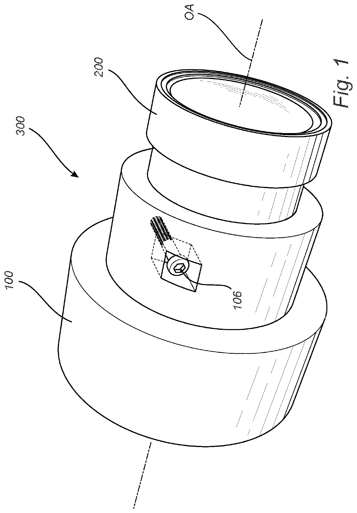
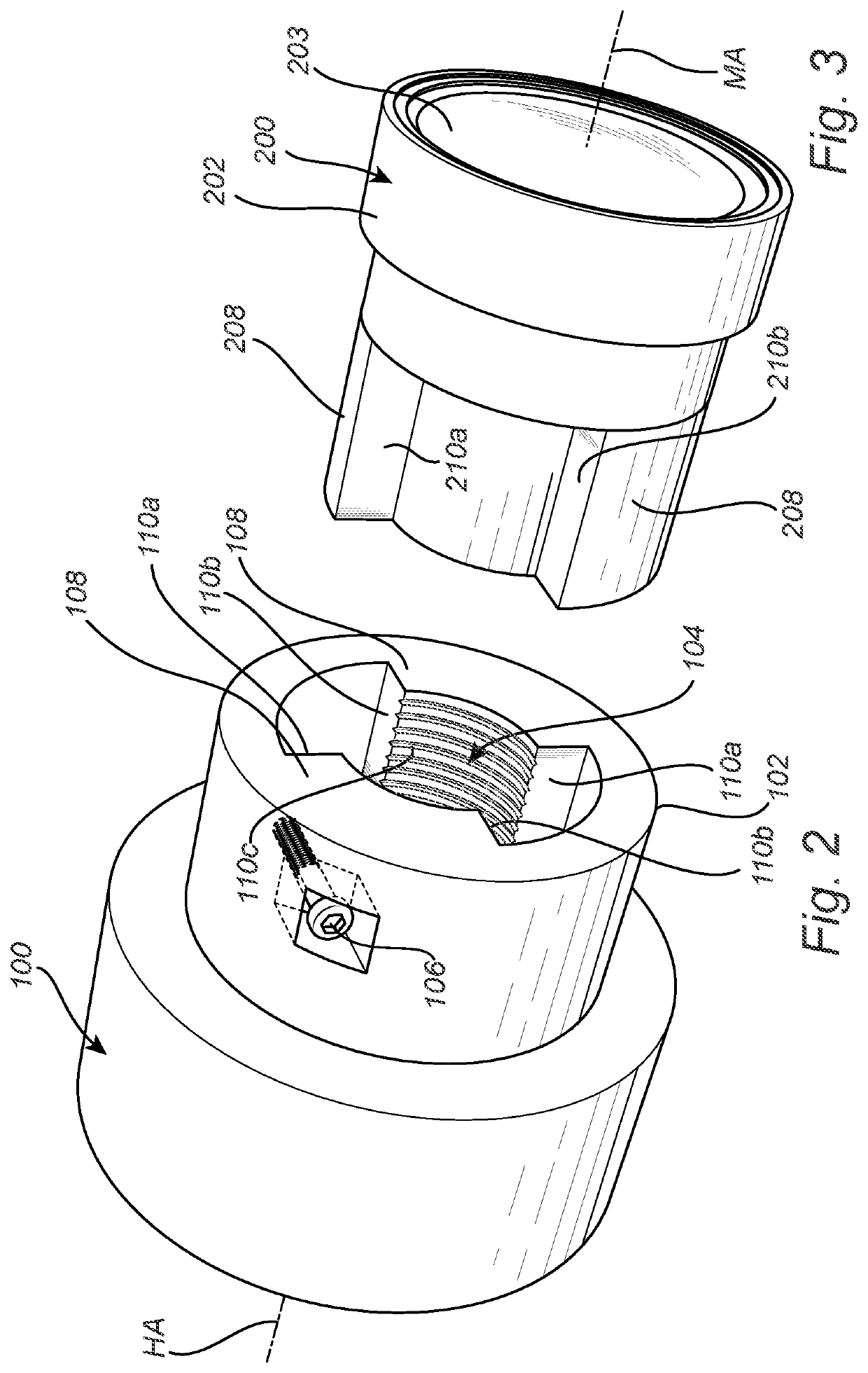
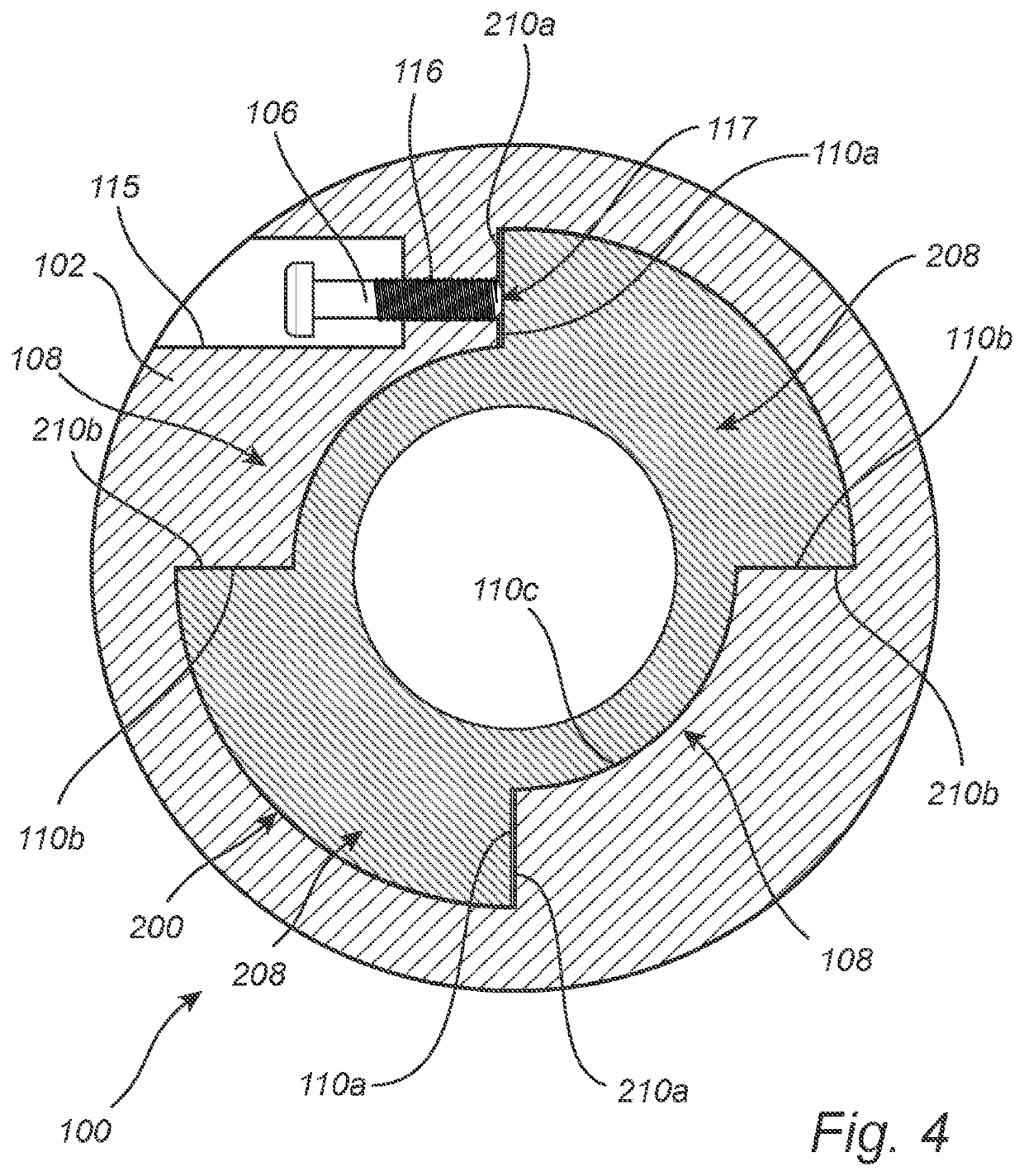
[0038]A lens arrangement 300 for a camera device will in the following be described with reference to FIGS. 1-4.

[0039]FIG. 1 illustrates an embodiment of the lens arrangement 300. The lens arrangement 300 comprises a lens holder 100 and a lens member 200 releasably attached to the lens holder 100. The lens holder 100 and the lens member 200 are aligned along an optical axis OA.

[0040]As evident from FIG. 2, the lens holder 100 comprises a section having a wall 102 surrounding a cavity 104. The lens holder further comprises a...


PUM


Abstract

A lens arrangement of a camera device includes a lens holder and a lens member, the lens member being slidingly received by the cavity by axial insertion of the lens member into the cavity such that the longitudinal lens holder axis coincides with the longitudinal lens member axis, wherein a locking force is applied by the locking member in a direction from the first lens holder surface section, the locking force being perpendicular to the plane, wherein the lens holder protrusion and the lens member protrusion are such aligned that the locking force applied by the locking member in the direction from the first lens holder surface section is applied to the first lens member surface section. The second lens member surface section engage the second lens holder surface section in response to the locking force applied to the first lens member surface section.

Description

CROSS-REFERENCE TO RELATED APPLICATION[0001]The present application claims priority to EP 19197572.1, filed Sep. 16, 2019, the entire contents of which are incorporated herein by reference.FIELD OF THE INVENTION[0002]The invention relates to a lens holder and a lens arrangement comprising such a lens holder. The invention further relates to a camera device comprising such a lens arrangement.BACKGROUND ART[0003]Modular cameras such as network cameras may be used in many different situations, both indoors and outdoors. The versatility of modular cameras has led to an increased demand for cost effective production of modular cameras. To meet this demand, it is desirable to reduce not only the cost of the components of the modular cameras, but also the costs associated with the assembly of the modular cameras.[0004]A modular camera normally comprises two separate parts; a sensor unit and a main unit connected to the senor unit via cable.[0005]The sensor unit may comprise a lens holder a...

Claims


Application Information

Patent Timeline
Patent Type & Authority Patents(United States)
IPC IPC(8): G02B7/02G02B7/14
CPCG02B7/14H04N23/54H04N23/45H04N23/50H04N23/57H04N23/55G03B17/14
Inventor BOKVIST, MALTEDANELIUS, JÖNS
Owner AXIS
Learn More