Hydrogen generation catalysts and systems for hydrogen generation

a technology of catalysts and hydrogen, applied in the direction of electrochemical generators, metal/metal-oxide/metal-hydroxide catalysts, physical/chemical process catalysts, etc., can solve the problems of catalyst cost and durability

Inactive Publication Date: 2007-07-26
ZHANG QINGLIN +3
View PDF3 Cites 14 Cited by
  • Summary
  • Abstract
  • Description
  • Claims
  • Application Information

AI Technical Summary

Problems solved by technology

Activity, durability and cost of the catalyst are the major barriers for meeting commercial specifications.

Method used


Image

  • Hydrogen generation catalysts and systems for hydrogen generation
  • Hydrogen generation catalysts and systems for hydrogen generation

Examples


example

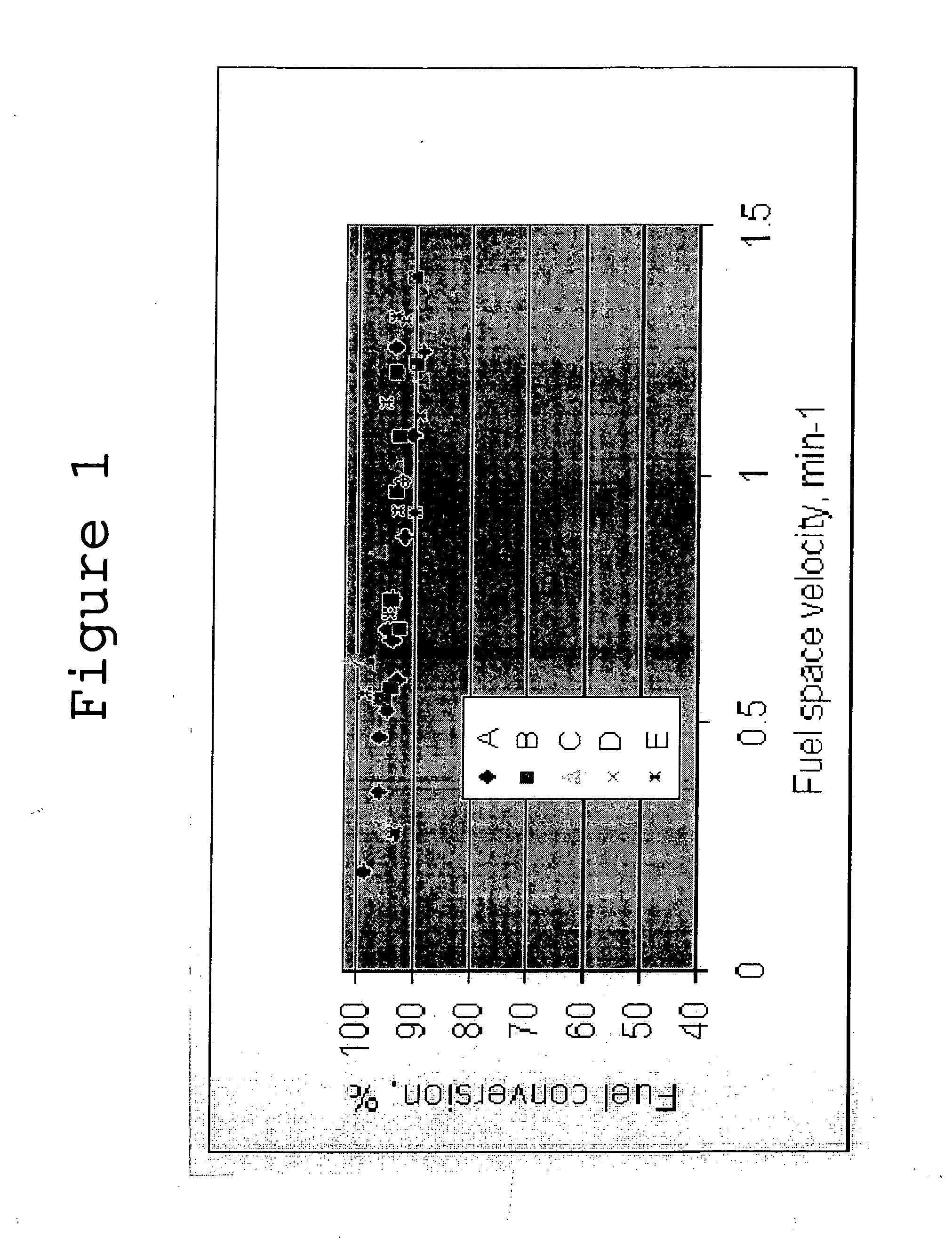
[0031] A catalyst comprising 0.6 wt-% ruthenium and 2 wt-% cobalt supported on a nickel metallic mat containing pressed nickel fibers and sintered nickel particles in a 40:60 ratio was used to evaluate durability and hydrogen generation activity.

[0032] Bulk and surface chemical composition were measured by ICP-MS and EDX to determine any catalyst degradation during use. Resulting data are summarized in Tables 2 and 3 below.

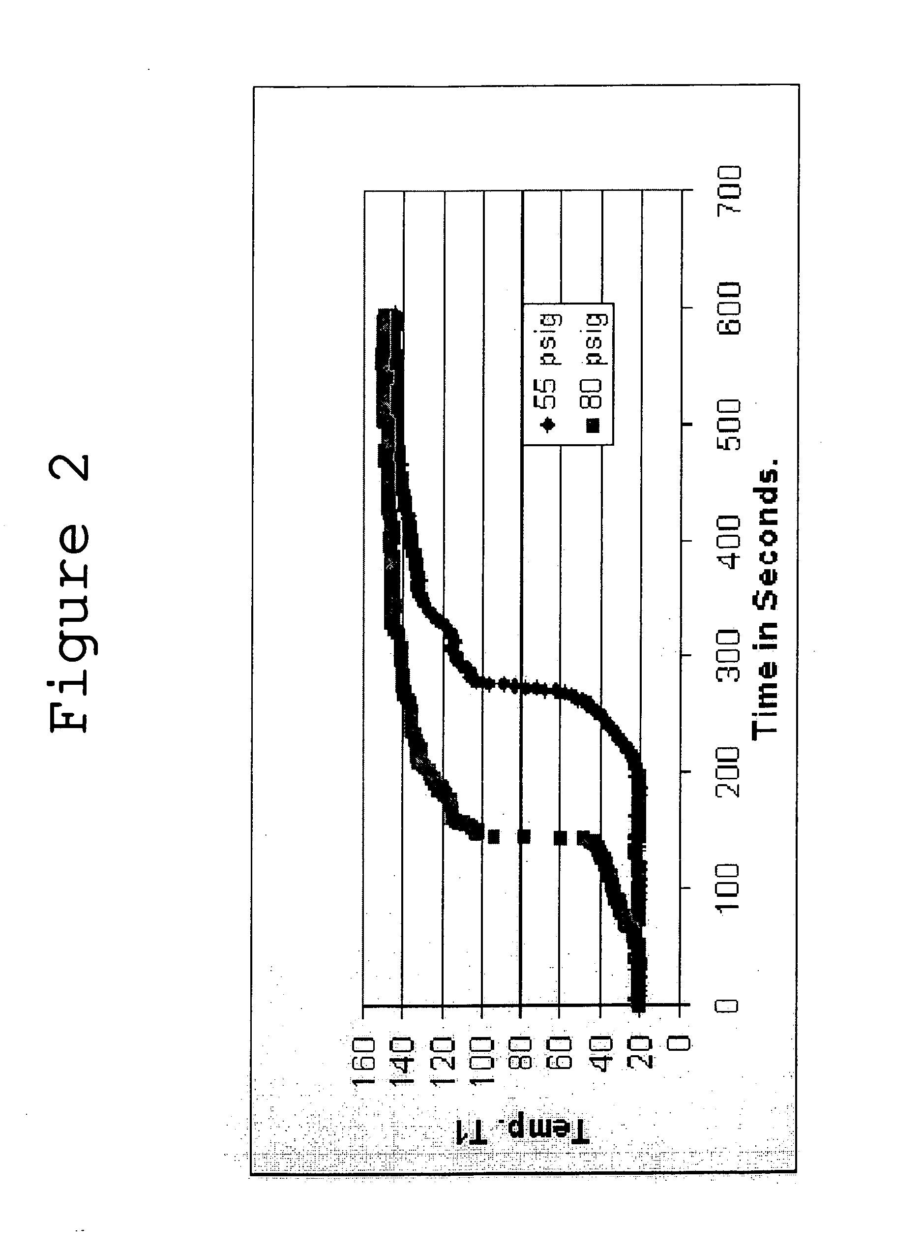
[0033] Fresh catalysts were subject to fuel treatments conducted under atmospheric pressure and using a 20 wt-% sodium borohydride and 3 wt-% NaOH fuel solution at about 70° C., as a way to simulate multi-cycle usage of the catalyst. For each test, 200 mL of fuel solution was added to a reactor immersed in a water bath preheated to about 30° C., and the reactor system thoroughly purged with hydrogen. Catalyst was then added to the reactor and stirred with a magnetic stirrer for 0.5 hours. Rate of hydrogen generation and reaction temperature were measured. Activi...


PUM

PropertyMeasurementUnit
Temperatureaaaaaaaaaa

Abstract

Supported catalysts and methods are provided to promote hydrogen generation from the hydrolysis of boron hydrides. The supported catalysts contain a supported metal comprising at least one transition metal selected from the group consisting of cobalt, ruthenium, zinc, molybdenum, manganese, titanium, tin, cadmium, and iridium, in an amount of from about 0.1 to about 20% by weight of the supported catalyst.

Description

[0001] This application is a continuation-in-part of U.S. application Ser. No. 11 / 167,608, filed on Jun. 28, 2005, the entire disclosure of which is incorporated by reference herein.FIELD OF THE INVENTION [0002] The present invention relates to catalysts and systems for the catalytic generation of hydrogen from, for example, aqueous chemical hydride solutions. BACKGROUND OF THE INVENTION [0003] Chemical hydrides are known hydrogen storage materials characterized by relatively high gravimetric hydrogen storage density. Chemical hydrides, such as alkali metal hydrides and metal borohydrides, can generate hydrogen through a hydrolysis reaction with water. For these chemical hydrides, the gravimetric hydrogen densities range from about 4 to about 9% by weight. Sodium borohydride (NaBH4) is of particular interest because it can be dissolved in alkaline water solutions with virtually no reaction until it contacts a catalyst. In this case, the stabilized alkaline solution of sodium borohyd...

Claims


Application Information

Patent Timeline
IPC IPC(8): B01J21/02
CPCB01J21/18B01J23/8913B01J23/892B01J35/1009B01J35/1014Y02E60/362B01J35/1023B01J35/1028B01J35/1061C01B3/065H01M8/065B01J35/1019Y02E60/36Y02E60/50B01J35/612B01J35/618B01J35/617B01J35/613B01J35/647B01J35/615
Inventor ZHANG, QINGLINWU, YINGSMITH, GREGORY M.BINDER, MICHAEL
Owner ZHANG QINGLIN
Why Eureka
Try Eureka