
Corrosion-protection by electrochemical deposition of metal oxide layers on metal substrates

a metal substrate and electrochemical technology, applied in electrophoretic coatings, coatings, chemistry apparatuses and processes, etc., can solve the problems of sludge containing heavy metals, chromating process disadvantages, and difficult to achieve the effect of preventing sludge from forming,

Inactive Publication Date: 2007-06-28
HENKEL KGAA
View PDF7 Cites 17 Cited by
  • Summary
  • Abstract
  • Description
  • Claims
  • Application Information

AI Technical Summary

Benefits of technology

[0025] Applicant has now surprisingly found that the problems related to the prior art processes can be overcome by coating a metal substrate to be provided with corrosion-protection and / or corrosion-resistance with a thin layer of at least one metal oxide selected from the group consisting of TiO2, Bi2O3 and ZnO by electrochemically depositing the metal oxide layer on the metal substrate.

Problems solved by technology

Technically simpler to perform, but less effective, is the simple application of a primer coat to a metal prior to lacquer-coating thereof.
For example, chromating processes are disadvantageous from both an environmental and an economic point of view owing to the toxic properties of the chromium and the occurrence of highly toxic sludge.
However, chromium-free wet processes, such as phosphating, as a rule, also result in the production of sludge containing heavy metals, which has to be disposed of at some expense.
Another disadvantage of conventional wet coating processes is that the actual coating stage frequently has to be preceded or followed by further stages, thereby increasing the amount of space required for the treatment line and the consumption of chemicals.
Although dry coating processes entail fewer waste problems, they have the disadvantage of being technically complex to perform (for example requiring a vacuum) or of having high-energy requirements.
The high operating costs of these processes are therefore a consequence principally of plant costs and energy consumption.
The article investigates above all the influence of deposition conditions on the morphology of the oxide layers; it does not disclose any practical application of the layers.
However, in these processes the metal originates from the metal substrate itself so that part of the metal substrate is destroyed during oxide layer formation.
However, the disadvantages of phosphating (necessity of several sub-stages, such as activation, phosphating, post-passivation, as well as the occurrence of phosphating sludge) are not overcome thereby.
However, this electrochemical deposition produces these layers in amorphous structure only.
However, this process requires the presence of peroxide, which causes the instability of the electrolyte solution.
However, these methods have several problems mentioned in the following:
The problems related to prior art physical deposition techniques (e.g. radio frequency magnetron sputtering, metal organic chemical vapor deposition and molecular beam epitaxy) are shown by the following: Since titanium dioxide layers with crystal structure are obtained at high substrate temperature, these layers cannot be obtained on material with melting point below 373 K. Further, such physical deposition techniques are very cost-intensive and difficult to manage so that such physical deposition techniques are inappropriate for industrial application.
Thus, these layers cannot be obtained on material with a melting point below 373 K.
The problems related to prior art electrolysis techniques are particularly shown by the following: TiO precursor-layers are obtained from electrolytes containing HF, NH3, peroxides and Ti ions etc. at pH-values below 4 by electrochemical deposition; due to the use of acidic HF-solutions, such electrolyte is environmentally non-friendly.
The existence of peroxide and nitrate ions exhibits the decrease in the stability of such electrolyte.
Since a TiO precursor-layer crystallizes as anatase or rutile structures only by using subsequent heat-treatment, these layers cannot be obtained on material with a melting point below 373 K.

Method used


Image

  • Corrosion-protection by electrochemical deposition of metal oxide layers on metal substrates
  • Corrosion-protection by electrochemical deposition of metal oxide layers on metal substrates
  • Corrosion-protection by electrochemical deposition of metal oxide layers on metal substrates

Examples


example 1

Example 1-1

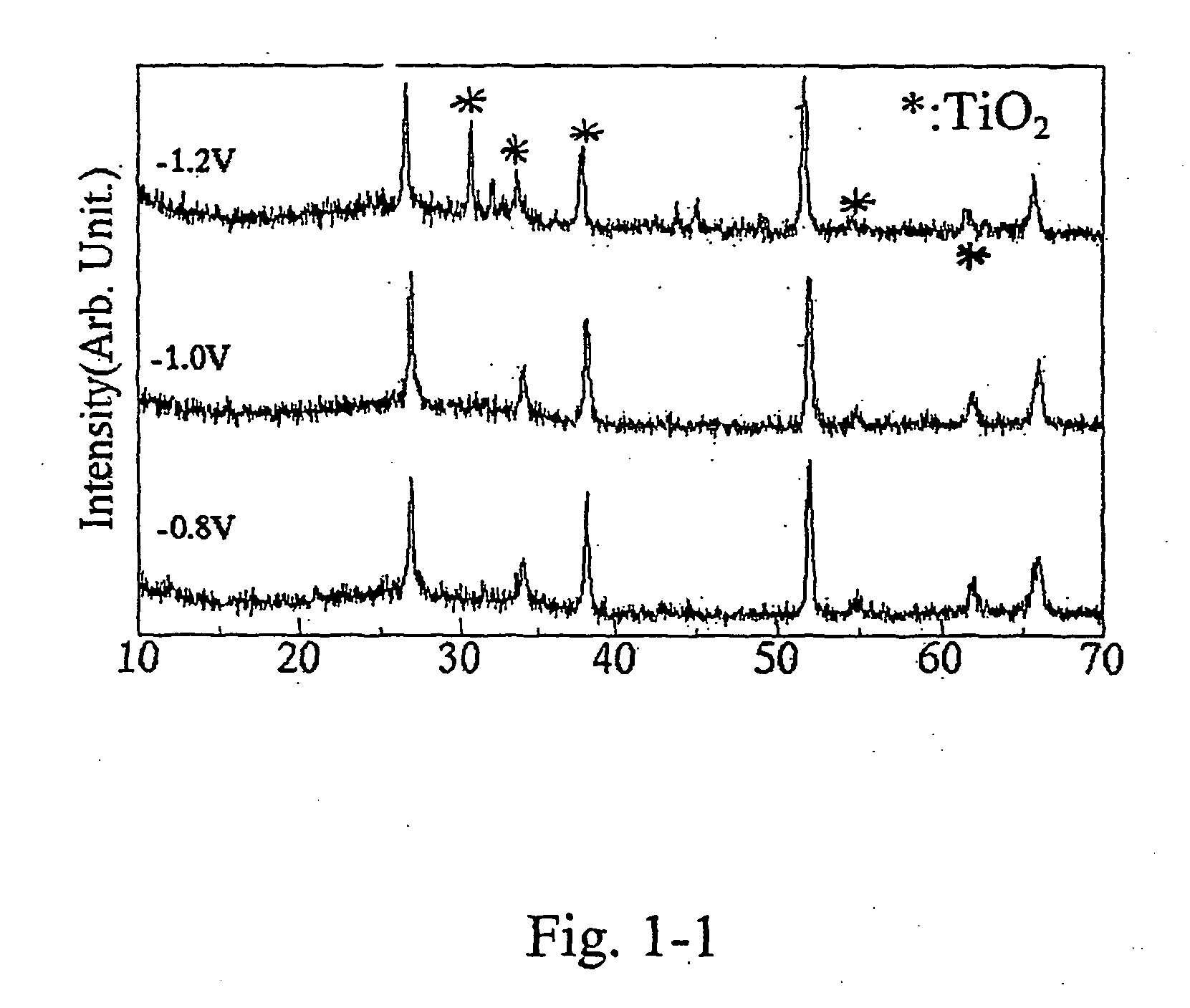
[0094] TiO2-layers were electrochemically grown from titanyl sulfate aqueous solution with sodium nitrate and sodium tartrate at cathodic potentials of −0.8 V, −1.0 V and −1.2 V, respectively. Titanyl sulfate concentration was 0.1 mol / L. Sodium tartrate concentration was 0.1 mol / L. Sodium nitrate concentration was 0.1 mol / L. A titanium sheet (99.999% purity) was used as an active anode. An Ag / AgCl-electrode was used as a reference. Electrolysis was carried out potentiostatically using a potentio / galvanostat (Hokuto Denko, HABF501) without stirring. Table 1-1 shows the electrochemical deposition conditions for the TiO2-layers of Example 1-1.

TABLE 1-1Electrochemical growth conditionsfor the TiO2-layers of Example 1-1Composition of the electrolyteTitanyl sulfate concentration0.1 mol / LSodium tartrate concentration0.1 mol / LSodium nitrate concentration0.1 mol / LAnode electrodetitanium sheet (99.999%)Substrate (cathodic electrode)NESA-glassReferring electrodeAg / AgClpH for the ...

example 1-2

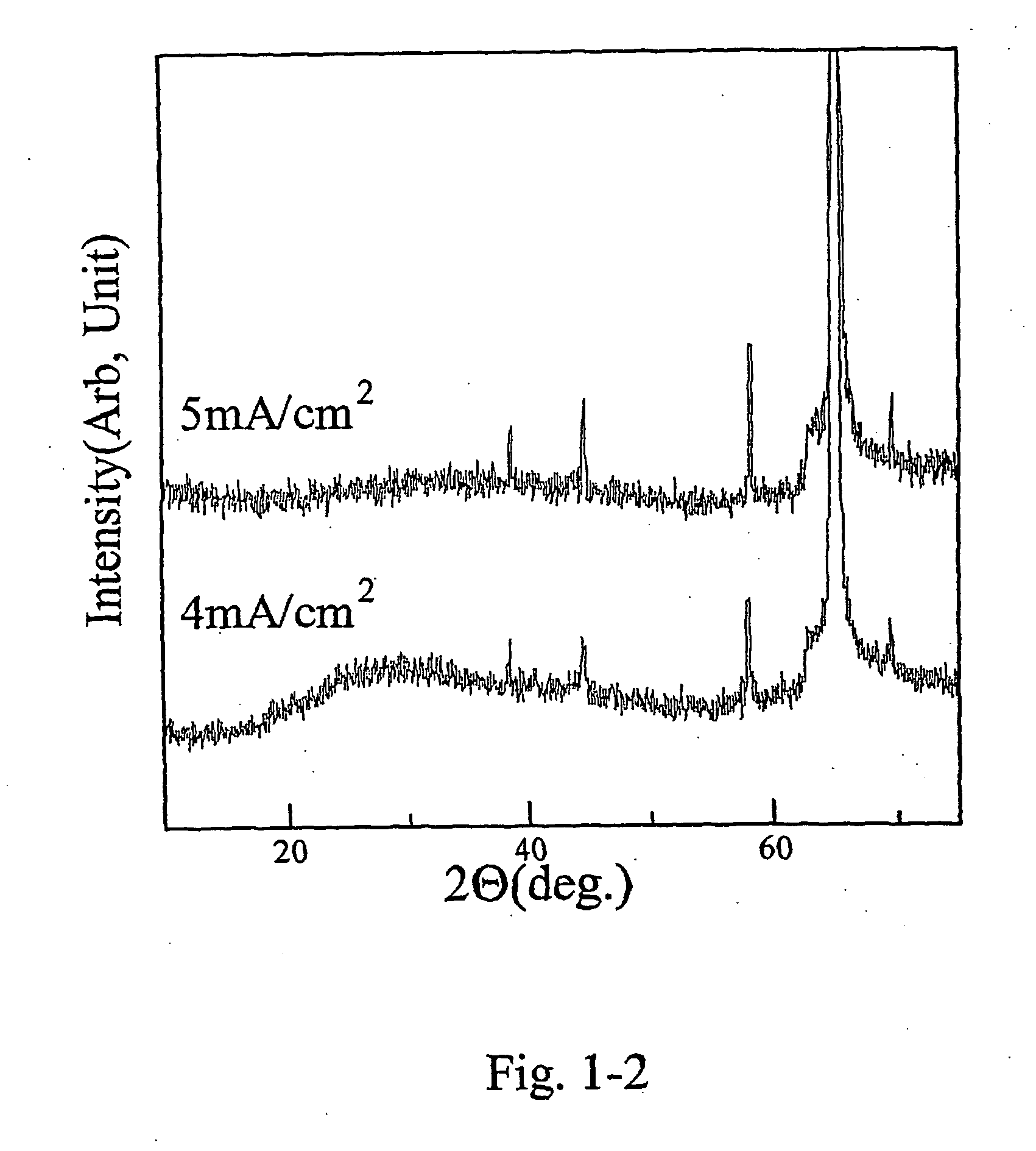
[0095] On aluminum sheet, TiO2-layers were electrochemically grown by using the electrolyte and the equipment mentioned above. A titanium sheet (99.999%) was used as the active anode, and an Ag / AgCl-electrode was used as a reference. Electrolysis was performed by using potentio / galvanostat (Hokuto Denko, HABF501) without stirring at −4 mA / cm2 and −5 mA / cm2 cathodic current density. The Coulomb values were constant values of 10 C / cm2, regardless of all electrochemical growth conditions. Table 1-2 shows the electrochemical deposition conditions for the TiO2-layers of Example 1-2. FIG. 1-2 shows the X-ray diffraction spectra of the TiO2-layers off Example 1-2 galvanostatically obtained. All diffraction lines were identified to those of TiO2.

TABLE 1-2Electrochemical growth conditionsfor the TiO2-layers of Example 1-2Composition of electrolyteTitanyl sulfate concentration0.1 mol / LSodium tartrate concentration0.1 mol / LSodium nitrate concentration0.1 mol / LAnode electrodetitanium sheet (9...

example 2

[0096] In Example 2, polycrystalline TiO2-layers were electrochemically grown on NESA-glass substrates from a 0.05 M titanium potassium oxalate dihydrate aqueous solution containing a 0.5 M hydroxylamine at 333 K by cathodic potentiostatic methods. The electrolytes were adjusted to pH=9 with KOH (aq.). A titanium sheet (99.999%) was used as active anode, and an Ag / AgCl-electrode was used as a reference. Electrolysis was performed by using potentiostatic / galvanostatic (Hokuto Denko, HABF501) without stirring at cathodic potential range of −1.3 V to −1.0 V. The Coulomb values were constant values of 10 C / cm2, regardless of all electrochemical growth conditions. Table 2-1 shows the electrochemical deposition conditions for the TiO2-layer of Example 2.

TABLE 2-1Electrochemical growth conditionsfor the TiO2-layers of Example 2Composition of electrolyteTitanium potassium oxalate0.05 mol / Ldihydrate concentrationHydroxylamine concentration 0.5 mol / LAnode electrodetitanium sheet (99.999%)Su...


PUM

PropertyMeasurementUnit
Temperatureaaaaaaaaaa

Abstract

The present invention relates to a process for providing a metal substrate with corrosion-protection and corrosion-resistance, respectively, as well as to the products thus obtainable. Said process comprises coating said metal substrate with a thin layer of at least one metal oxide selected from the group consisting of TiO2, Bi2O3 and ZnO, preferably TiO2, by electrochemically depositing said metal oxide layer on at least one surface of said metal substrate. At the same time, said metal oxide layer may serve as a primer layer for subsequent coating treatment (e.g. coating with organic materials, such as for instance lacquers, varnishes, paints, organic polymers, adhesives, etc.).

Description

CROSS-REFERENCE TO RELATED APPLICATIONS [0001] This application is a continuation under 35 USC Sections 365(c) and 120 of International Application Number PCT / EP2004 / 014140, having an international filing date of Dec. 11, 2004, published in English on Jul. 14, 2005 as International Publication Number WO2005 / 064045A1, and claiming priority to European Application Number EP 03029544.8 filed on Dec. 22, 2003, both of which are incorporated herein by reference in their entirety.FIELD OF THE INVENTION [0002] The present invention relates to a process of providing a conductive metal substrate with corrosion-protection or corrosion-resistance, respectively, by electrochemically depositing a metal oxide layer on said metal substrate. At the same time, such metal oxide layer deposited electrochemically may serve as an appropriate primer layer for subsequent coating treatment (e.g. coating with organic materials, such as for instance lacquers, varnishes, paints, organic polymers, adhesives, e...

Claims


Application Information

Patent Timeline
IPC IPC(8): B32B15/04C25D11/00C25D9/08C25D13/20
CPCC25D9/08C25D13/20
Inventor ISHIKAZI, HIROKISCHWEINSBERG, MATTHIASITO, SEISHIROWIECHMANN, FRANK
Owner HENKEL KGAA
Learn More