
Ball penetrometer for soft soils testing

a penetrometer and soft soil technology, applied in the field of ball penetrometers, can solve the problems of high degree of conservatism, all of the above tools have limitations, and the ability of cone penetrometers to accurately profile soft sediments is relatively poor

Active Publication Date: 2007-06-07
BENTHIC GEOTECH PTY LTD
View PDF8 Cites 29 Cited by
  • Summary
  • Abstract
  • Description
  • Claims
  • Application Information

AI Technical Summary

Benefits of technology

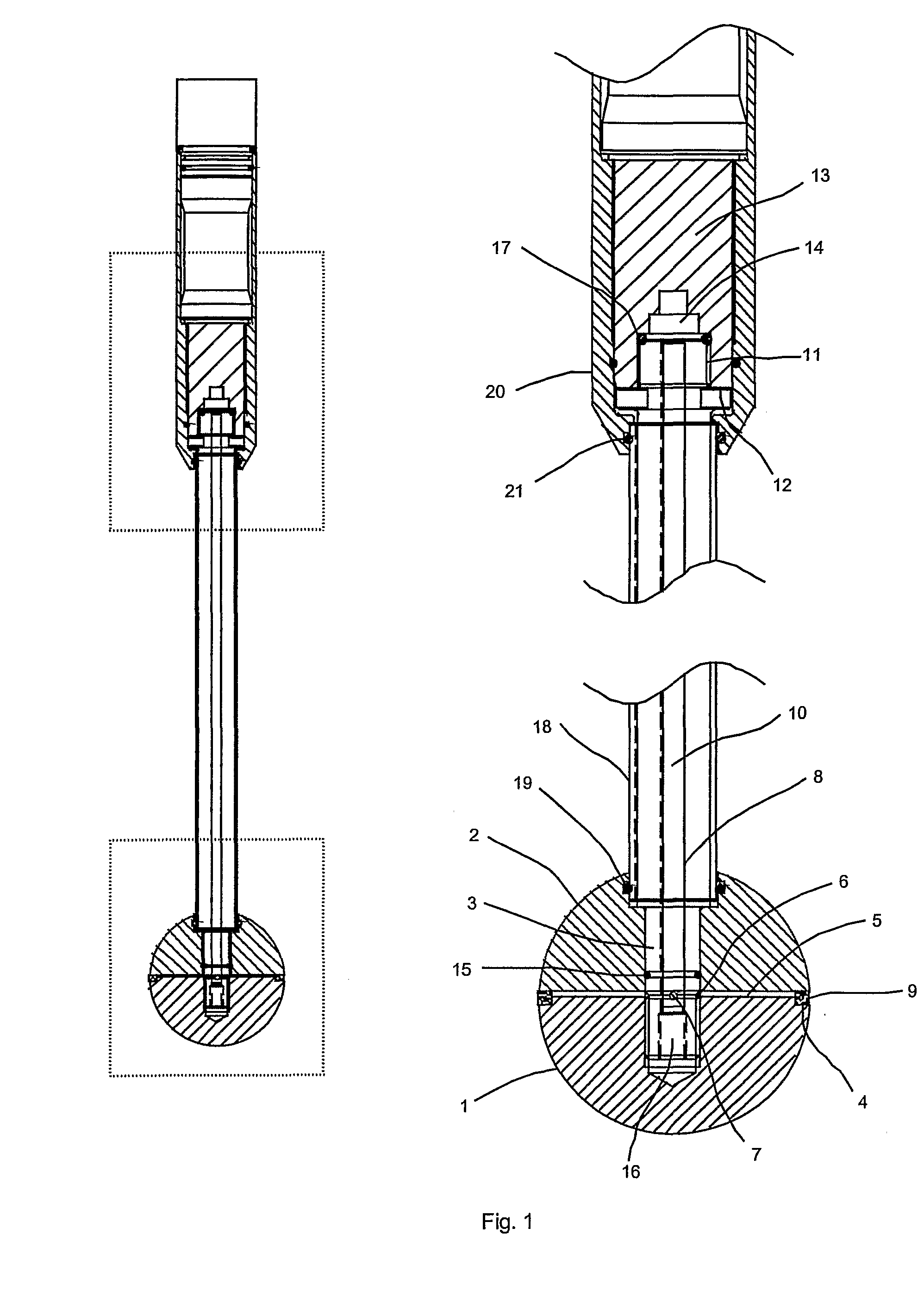
[0029] In one particular embodiment, the shaft is loosely enclosed by a tubular antifriction sleeve which is recessed at its lower end into the top of the ball and at its upper end into the outer sleeve of the transducer module. According to further aspects of a particular embodiment of the invention, the antifriction sleeve is peripherally sealed by flexible sealing members, for example o-rings, at each end. These o-ring seals accommodate minute axial displacement of the ball and shaft assembly arising from reaction forces on the ball during soil penetration and withdrawal. The ball and shaft assembly can thus freely sense the true axial load acting on the ball, in isolation from soil friction on the shaft. Load sensing is bi-directional, that is, measuring both downwards penetration into undisturbed soil and upwards thrust as a measure of remoulded shear strength.
[0030] According to the present invention, measurement of soil shear strength may be accompanied by measurement of pore water pressure, or vice versa. Known ball penetrometer probes do not provide this capability. According to a further particular embodiment of the present invention, there can be provided a peripheral ring of porous material around the ball. The porous ring connects via internal fluid-filled galleries in the ball and shaft to a pressure transducer in the attached electronics module. The porous ring allows the internal fluid pressure to equilibrate with the external fluid pressure surrounding the ball to provide measurement of dynamic pore water pressure. Preferably, the porous ring is optimally positioned at the mid-point of the ball where it is least affected by creep strain of soil during the course of dissipation testing.

Problems solved by technology

However, all of the above tools have limitations.
Key disadvantages with the use of CPT devices in soft soils include: a) cone correction factors, which are used to convert CPT tip resistance to soil shear strength, are empirically based and vary widely, depending on the type and state of the soil undergoing test.
Uncertainties associated with the application of cone factors typically leads to a high degree of conservatism in design; b) CPT devices (particularly when subjected to high ambient water pressures), require a correction for the effects of water pressure acting on the unequal areas of the cone tip.
This correction is typically very significant in soft sediments, which mobilise relatively low cone tip pressures and high excess pore water pressures; c) cone penetrometers have a relatively poor capacity to accurately profile soft sediments.
These factors combine to reduce the available resolution of the device.
Disadvantages of the VST include: a) the VST cannot provide a continuous measurement of the shear strength profile with depth; b) the VST is not suitable for measuring the shear strength of dilatant, coarse grained soils; c) knowledge of the soil type is required for correct interpretation of VST results.
A key disadvantage of the T-Bar penetrometer for deployment via a drillstring of relatively small diameter, lies with the required geometry of the horizontal bar.
This presents problems for many offshore drilling units, particularly remotely operated seabed drilling units, which currently are incapable of handling these large dimension tools.
SBP probes disclosed in the literature are individual dedicated instruments with simple built-in load cells close to the ball, with no capability for optional measurement of pore water pressure.
Another alternative for so-called “measurement while drilling” uses a “mud pulse” system that transmits data via pressure pulses in the drilling fluid up the drill string, however this is impractical for small diameter tools.

Method used


Image

  • Ball penetrometer for soft soils testing
  • Ball penetrometer for soft soils testing

Examples


embodiment

Preferred Embodiment

[0044] With reference to FIG. 1, a ball penetrometer according to the present invention includes a lower hemispherical body 1 and an upper hemispherical body 2, the hemispheres being of equal radius, concentrically arranged and rigidly attached on their axis of symmetry to the lower end of a shaft 3 to form a spherical probe assembly. The hemispherical bodies have uniform outer surfaces of defined or known roughness.

[0045] The upper face of lower hemisphere 1 is provided with an outer circumferential groove 4 and a number of radial grooves forming interconnecting passages 5 between the outer groove 4 and a corresponding annular passage 6 formed by a circumferential groove in shaft 3. Annular passage 6 further connects via a number of radial passages 7 to an axial passage 8 in shaft 3. Preferably, though not necessarily, there are four radial grooves forming interconnecting passages 5, and there are two radial passages 7.

[0046] Circumferential groove 4 holds a r...


PUM


Abstract

A ball penetrometer probe for in situ measurement of soft soil properties, particularly in the seabed, comprises a spherical body and slender shaft assembly, and either individually or in combination, an anti-friction sleeve enclosing the shaft and / or a peripheral porous ring on the spherical body with connecting internal passages through the shaft assembly, the shaft being adapted to attach to an electronic transducer module. The ball penetrometer is deployed to penetrate the soil bed, to continuously measure the soil bearing forces resisting penetration and withdrawal of the ball, to optionally measure the pore water pressure of the soil in contact with the ball and to transmit the measurement data from the probe to a remote operating station, either by wireless means such as an acoustic transducer or via a wired electrical connection.

Description

TECHNICAL FIELD [0001] The present invention relates to a method and apparatus for investigating soil properties of soft soils, for example seabeds or other submerged beds such as lakebeds, etc., and in particular, to an improved ball-type penetrometer and associated method of use thereof. BACKGROUND ART [0002] Determining the soil characteristics of the seabed is an essential part of the geotechnical design of offshore installations, which can include structures for oil and gas developments, seabed anchorages, submarine pipelines and cables, and wind energy developments. The in situ properties of seabed soils profoundly influence the design and performance of structures that interact with the seabed. The trend in the offshore energy industry towards working in deep and ultra-deep water, where soft sediments predominate, places increasing importance on the ability to accurately measure soft soil strength and deformation parameters. Examples of prior art documents describing known te...

Claims


Application Information

Patent Timeline
IPC IPC(8): G01N3/42G01N33/24E02D1/00E21B49/00E02D1/02G01N3/00G01N3/06
CPCE02D1/022E21B49/001E21B49/006G01N3/064G01N3/42G01N2203/0082
Inventor KELLEHER, PATRICK J.PAYOR, STEPHEN DAVIDSHIELS, JAMES AUSTIN
Owner BENTHIC GEOTECH PTY LTD
Learn More