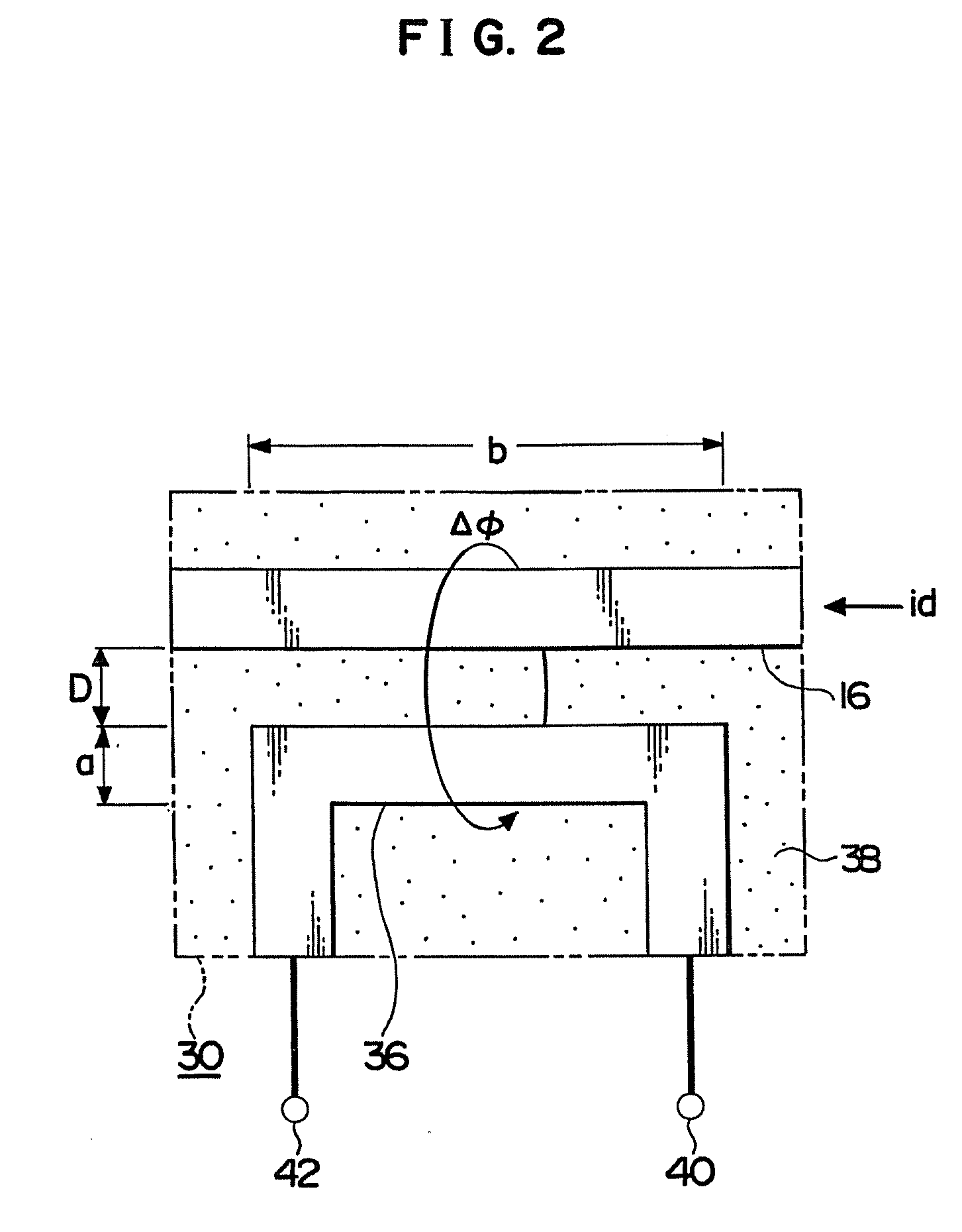
A current
route including the FL tube to which AC output from the inverter is supplied corresponds to a segment of wiring, leading from a winding of an inverter
transformer, on the
high voltage side thereof, to the FL tube, and is susceptible to deformation under
external pressure because it is long and thin in size since it passes by way of a multitude of members such as windings of the inverter transformer, a conductor pattern on a
printed circuit board, connectors, wiring, etc.
With a cellular phone and a note type
personal computer, an installation space for the FL tube lighting device is particularly narrow, so that thin wiring leading from the inverter to the FL tube is susceptible to deformation due to
external pressure.
In case that disconnection occurs to the above-described current route of the inverter, flow of current is
cut off by the disconnection, however, there arises a risk of the current route being maintained because the
constant current at the
high voltage flows in the current route of the FL tube, and a rise in
voltage occurs at the time of the disconnection, thereby resulting in
continuation of discharge at a spot of the disconnection.
Since it is impossible to know behavioral anomaly from a lighting state, discovery of that behavioral anomaly is delayed.
However, such a protection device is complex in configuration because it requires the monitor circuit for taking out the output of the inverter and monitoring thereof, a
microcomputer for determining whether the
monitoring pulse voltage is normal or anomalous, and so forth, and also since the output of the inverter is taken out to an outside, the inverter side is forced to take measures to cope with the change in an operating condition.
However, the discharge lamp lighting device requires the
high frequency voltage detection
resistor directly connected to the discharge lamp, and also the difference in voltage at the time of normal and that at the time of anomaly (at the time of discharge) is determined by a voltage dividing ratio of a resistance
voltage divider circuit configured by the
high frequency voltage detection
resistor and a threshold level of a switching
transistor, and so forth, and hence the accuracy of determination of whether it is normal or anomalous is low, and also there is a risk of stoppage of operation by a level change at the time of normal.
This
overcurrent detecting device is not a device which detects change in a circuit current due to discharge occurring a current route or a load side.
When discharge occurs to a disconnection spot, a voltage value or current value representing discharge is increased inside the inverter, but the amount of change is small, and hence even if the detection voltage is simply compared with a reference voltage, when the difference in level therebetween at the time of anomaly and normal is small, an erroneous operation is easy to occur, and hence it is not practical.
In order to enhance accuracy of the detection of disconnection discharge or
dielectric breakdown discharge between high and
low voltage parts, a circuit having the combination of a differentiation circuit, a
timer circuit and so forth is required, which however renders the circuit complex, which increases in manufacturing cost by adding a circuit like this to the inverter, resulting in lack of practice.
In the case where the amount of change in waveforms is small at the time of normal behavior and at the time of discharge such as a very small discharge, sufficient accuracy of detection cannot be obtained even if a differentiation circuit is used, so that an erroneous operation is easy to occur and it lacks in reliability.
However, these problems are not disclosed in the Publications No. 6-140173, No. 11-121190 and No. 9-113546, and means for solving the problems is not presented either.
Further, an obstacle due to very small discharge of an LCD is a defect due to
assembly work of the LCD.
Although that defect is detected by a visual confirmation and so on, certainty and reliability of that detection are lower.
Many of ground-fault discharge occurring between a high-voltage part and the ground around thereof are due to damage occurring in a covering of a high-voltage wiring, engagement between parts of wiring, a tear of an insulating tube of a soldered part, and so on, and is also due to an impression of stress to semiconductors in the LCD.
Further, disconnection discharge of a high-voltage current route is due to disconnection of a soldered part, contact fault of a connector, disconnection of a wiring, and so on.
Although an electric detection method of discharge like this is performed by observation of current waveform, preparation of a
testing equipment and time of a test are longer.
Even a product to which such a test has been performed, a detection of a fuming obstacle occurring after the lapse of time is difficult.


