
Biomagnetic field measurement apparatus having a plurality of magnetic pick-up coils

a biomagnetic field and measurement apparatus technology, applied in the field of biomagnetic field measurement apparatus, can solve the problems of fragmented partial information, signal strength decline or measurement, and inability to regulate the distance between the sensor and the head surface, and achieve the effect of more ease and high sensitivity

Inactive Publication Date: 2011-08-30
HITACHI LTD
View PDF5 Cites 12 Cited by
  • Summary
  • Abstract
  • Description
  • Claims
  • Application Information

AI Technical Summary

Benefits of technology

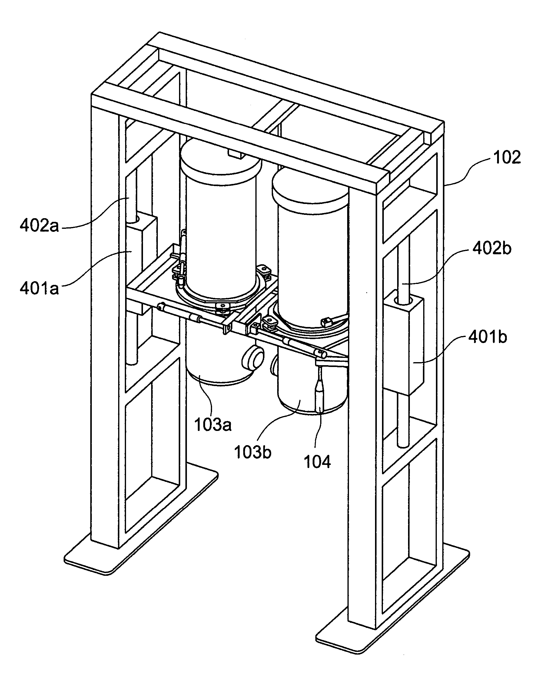
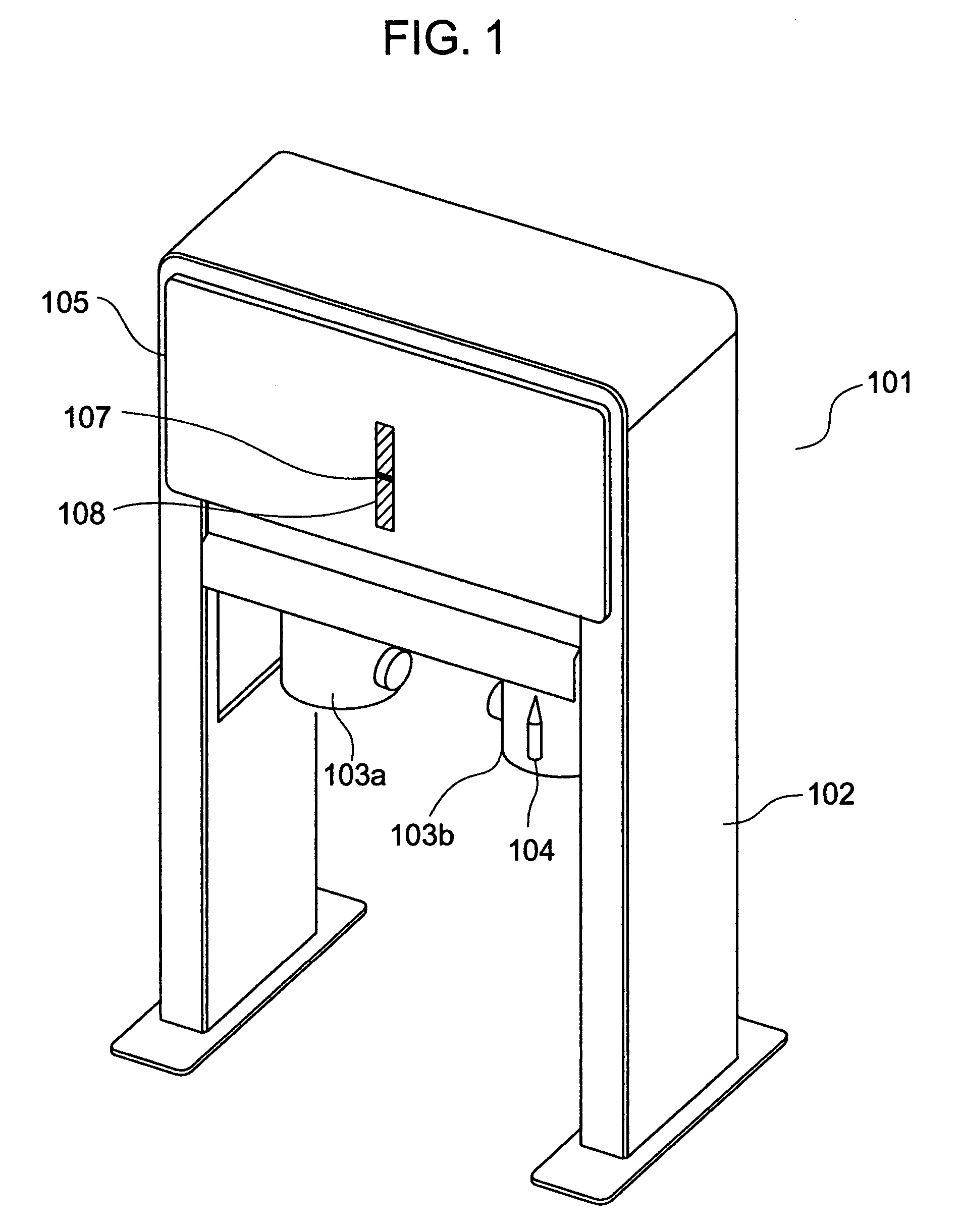
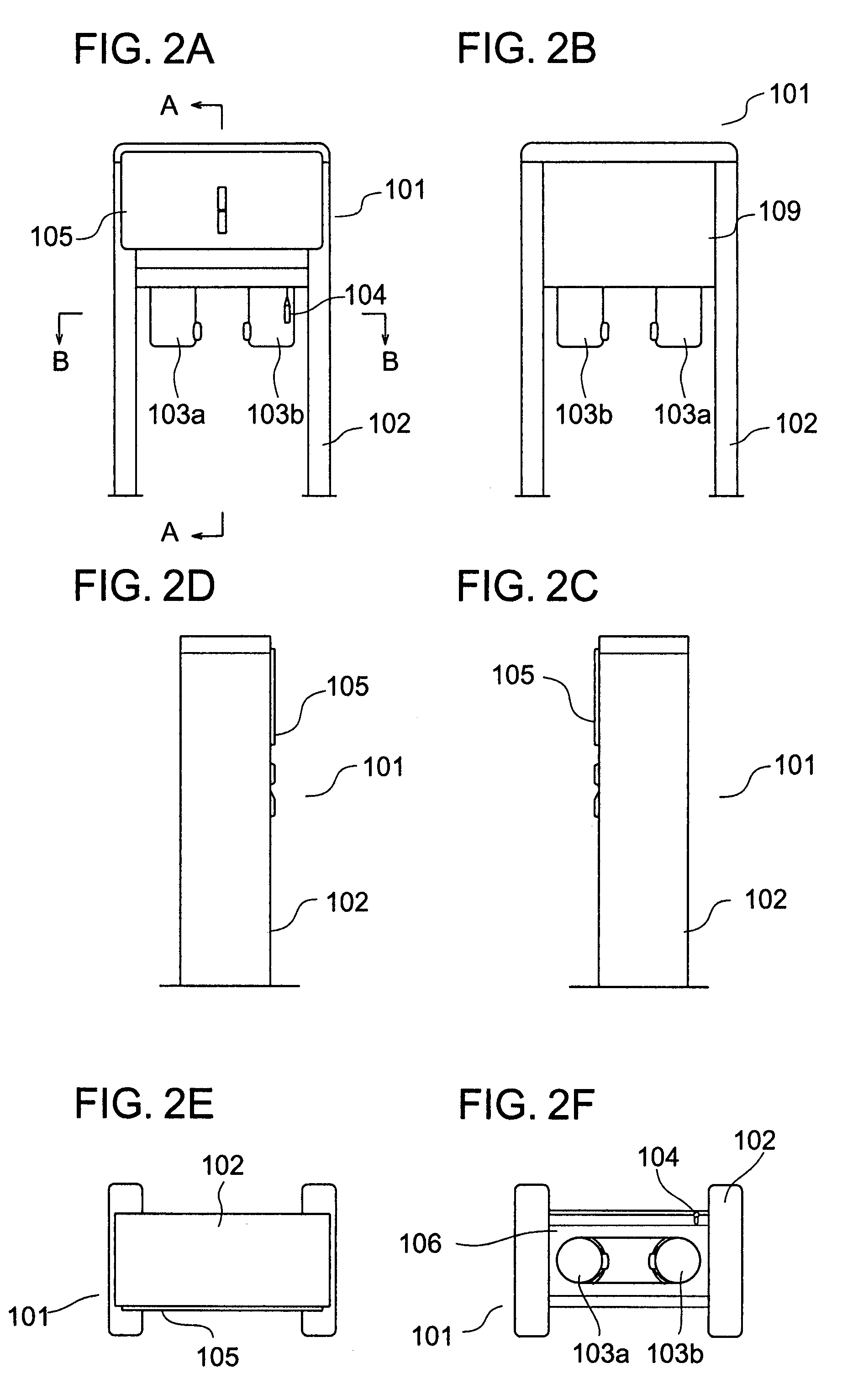
The present invention provides a biomagnetic field measurement apparatus that can detect cerebral magnetic fields with higher sensitivity and ease compared to conventional art. The apparatus includes two independent cryostats with SQUID fluxmeters that can interlock with each other and maintain a mirror image relation. The cryostats can move vertically, horizontally, and rotate while maintaining the mirror image relation. The apparatus also includes a gantry for supporting and driving the cryostats, a cover for efficient maintenance work, and conductive paint for shielding electromagnetic waves. The apparatus can detect cerebral magnetic fields with high sensitivity and ease.

Problems solved by technology

Therefore, the distance between the sensor and the head surface cannot be regulated.
This poses a problem that the signal strength decreases or measurement cannot be conducted.
Furthermore, there is a problem that only partial information is obtained fragmentarily even if a plurality of sensors are driven individually and sufficient measurement cannot be conducted.
In this method, there is a problem that the environmental magnetic field is not weakened sufficiently in the case where the environmental magnetic field is strong as in the magnetic shieldless environment.
In this method, there is a problem that the magnetic signal which is a detection object is also weakened although the environmental magnetic field is weakened.

Method used


Image

  • Biomagnetic field measurement apparatus having a plurality of magnetic pick-up coils
  • Biomagnetic field measurement apparatus having a plurality of magnetic pick-up coils
  • Biomagnetic field measurement apparatus having a plurality of magnetic pick-up coils

Examples


Embodiment Construction

[0046]Hereafter, an embodiment of the present invention will be described in detail with reference to the drawings. In the drawings, components having the same function are denoted by like reference characters.

[0047]As a superconducting material forming pick-up coils used in the apparatus in the embodiment described hereafter, a low temperature superconducting material having a low temperature superconducting transition temperature and acting as a superconductor at a low temperature (for example, the liquid helium temperature), or a high temperature superconducting material having a high temperature superconducting transition temperature and acting as a superconductor at a high temperature (for example, the liquid nitrogen temperature) can be used. A superconducting material having a superconducting transition temperature between the liquid helium temperature and the liquid nitrogen temperature, or a superconducting material having a superconducting transition temperature higher tha...


PUM


Abstract

A biomagnetic field measurement apparatus capable of easily bringing the sensor planes close to the head surface of the subject and capable of detecting cerebral magnetic fields of the left brain and the right brain simultaneously with a higher sensitivity is provided by disposing two independent cryostats holding SQUID fluxmeters in the mirror image relation to each other. The two cryostats move vertically and horizontally and rotate while interlocking with each other and maintaining the mirror image relation to each other. A gantry holding the cryostats has a function of suppressing vibration of the cryostats and has a gate shape.

Description

INCORPORATION BY REFERENCE[0001]The present application claims priority from Japanese application JP2006-273566 filed on Oct. 5, 2006, the content of which is hereby incorporated by reference into this application.BACKGROUND OF THE INVENTION[0002]The present invention relates to a biomagnetic field measurement apparatus intended to detect a magnetic field mainly generated from a brain.[0003]In a magnetoencephalograph for measuring a magnetic field (cerebral magnetic field) generated from a brain, a large number of pick-up coils are arranged over the whole-head surface with the object of mapping the electrophysiological activity of cerebral nerves. The magnetoencephalograph of this kind is called whole-head type magnetoencephalograph because the pick-up coils are arranged so as to cover the whole head for the purpose of measurement (see, for example, Patent Document 1). A merit of the whole-head type magnetoencephalograph is that signals of the whole cerebral hemisphere can be measur...

Claims


Application Information

Patent Timeline
Patent Type & Authority Patents(United States)
IPC IPC(8): A61B5/05
CPCA61B5/04008A61B5/245
Inventor SEKI, YUSUKEKANDORI, AKIHIKOOONUMA, MITSURU
Owner HITACHI LTD
Learn More