
Apparatus of catalytic gasification for refined biomass fuel at low temperature and the method thereof

a technology of biomass fuel and catalytic gasification, which is applied in the direction of combustible gas purification/modification, physical/chemical process catalysts, bulk chemical production, etc., can solve the problems of reducing requiring a lot of energy, and requiring a large amount of energy, etc., to achieve the reduction of the oxygen consumption required to maintain the operation temperature, the effect of compact apparatus and low cos

Inactive Publication Date: 2007-05-03
KOREA INST OF ENERGY RES
View PDF2 Cites 66 Cited by
  • Summary
  • Abstract
  • Description
  • Claims
  • Application Information

AI Technical Summary

Benefits of technology

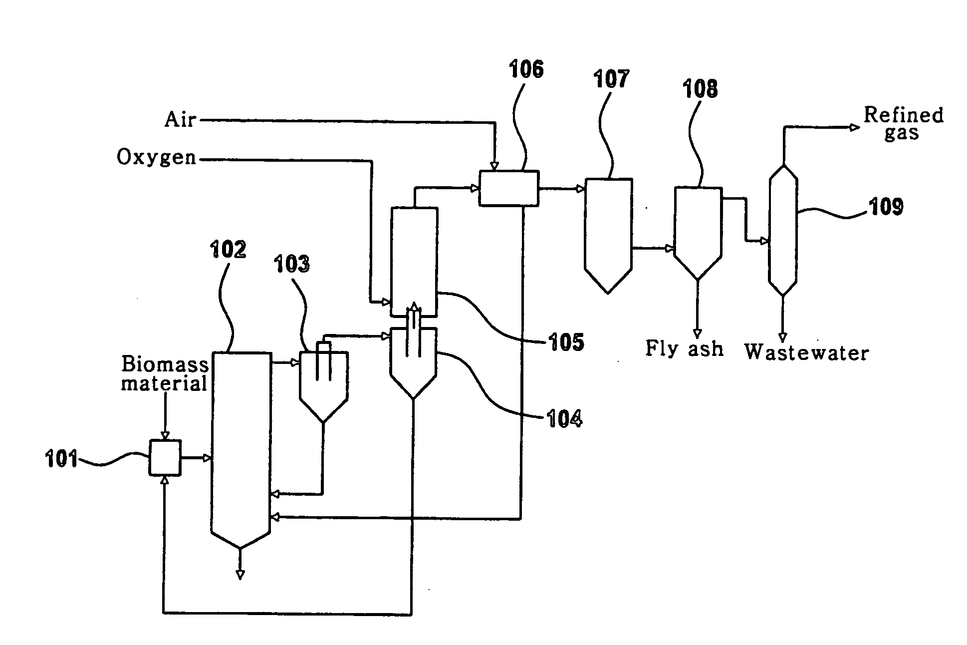
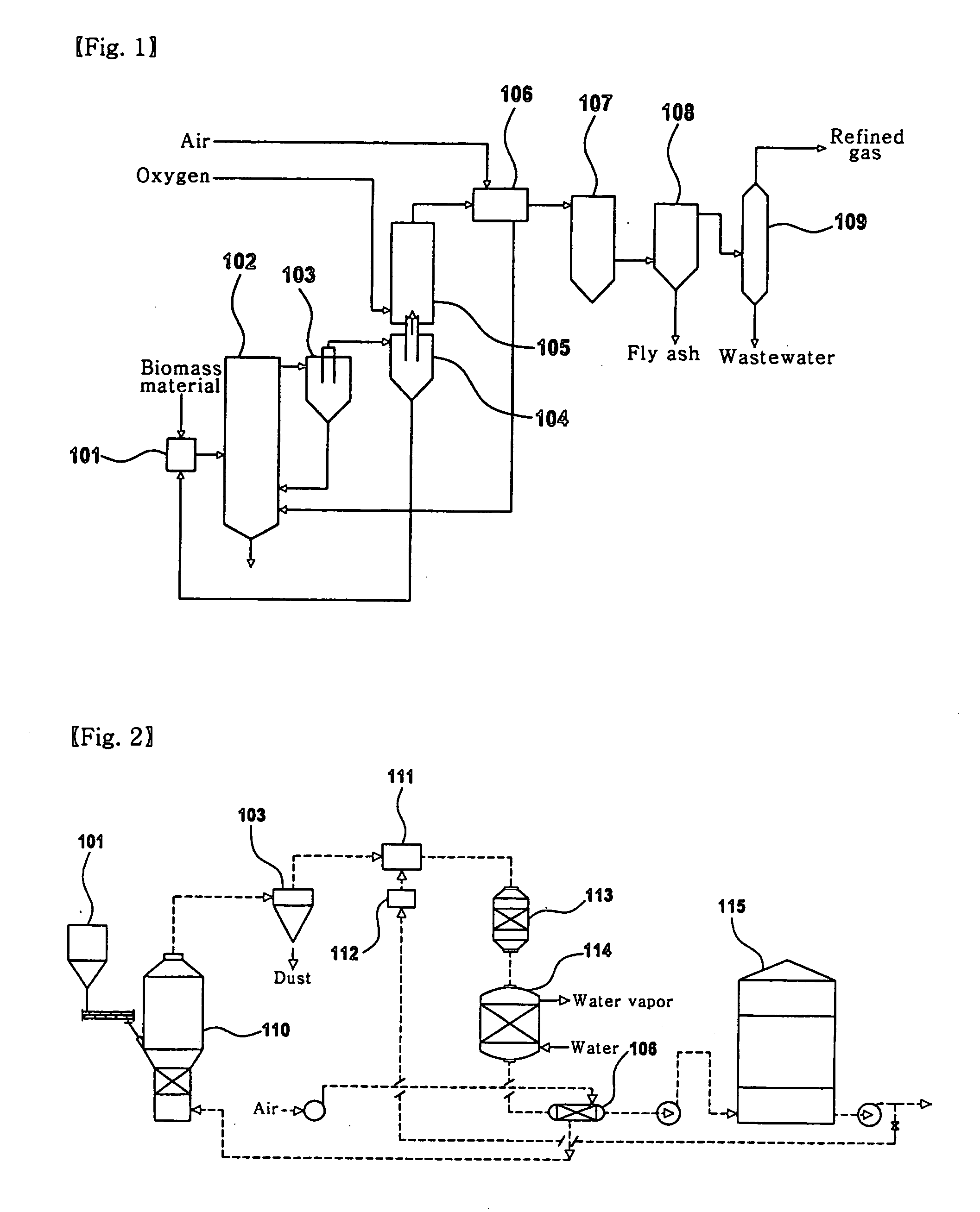
[0031] According to the present invention, the gasification of a fuel which is initiated at a temperature lower than that of a single fuel material may be conducted at a temperature which is further decreased by using a catalyst. Thereby, oxygen consumption required to maintain the operation temperature is decreased, thus a desired fuel may be inexpensively produced. In addition, since the operation temperature of a gasifier is low, little heat is released and a slagging treatment system is not needed, thereby realizing a compact apparatus. In addition, a gas product obtained by using a smaller amount of air in the present invention has the same caloric value as a gas product resulting from conventional gasification using oxygen, therefore generating economic benefits.
[0032] The present invention pertains to clean energy producing techniques for converting a highly refined mixture comprising sludge and coal into an inexpensive gas fuel having a high caloric value.
[0033] The gasification of the refined mixture comprising sludge / coal / oil is initiated, along with a material having a high initiation temperature of gasification, at a temperature lower than that of a single component. Thus, gasification may be performed for a short time, hence achieving rapid gasification. A low ash content and easy control of fly ash at a low temperature make it easier to decrease the size of an apparatus, leading to saved energy and efficient operation. Moreover, since a heavy metal and a salt are present in a very small amount, a combustion post-treatment system is not needed.
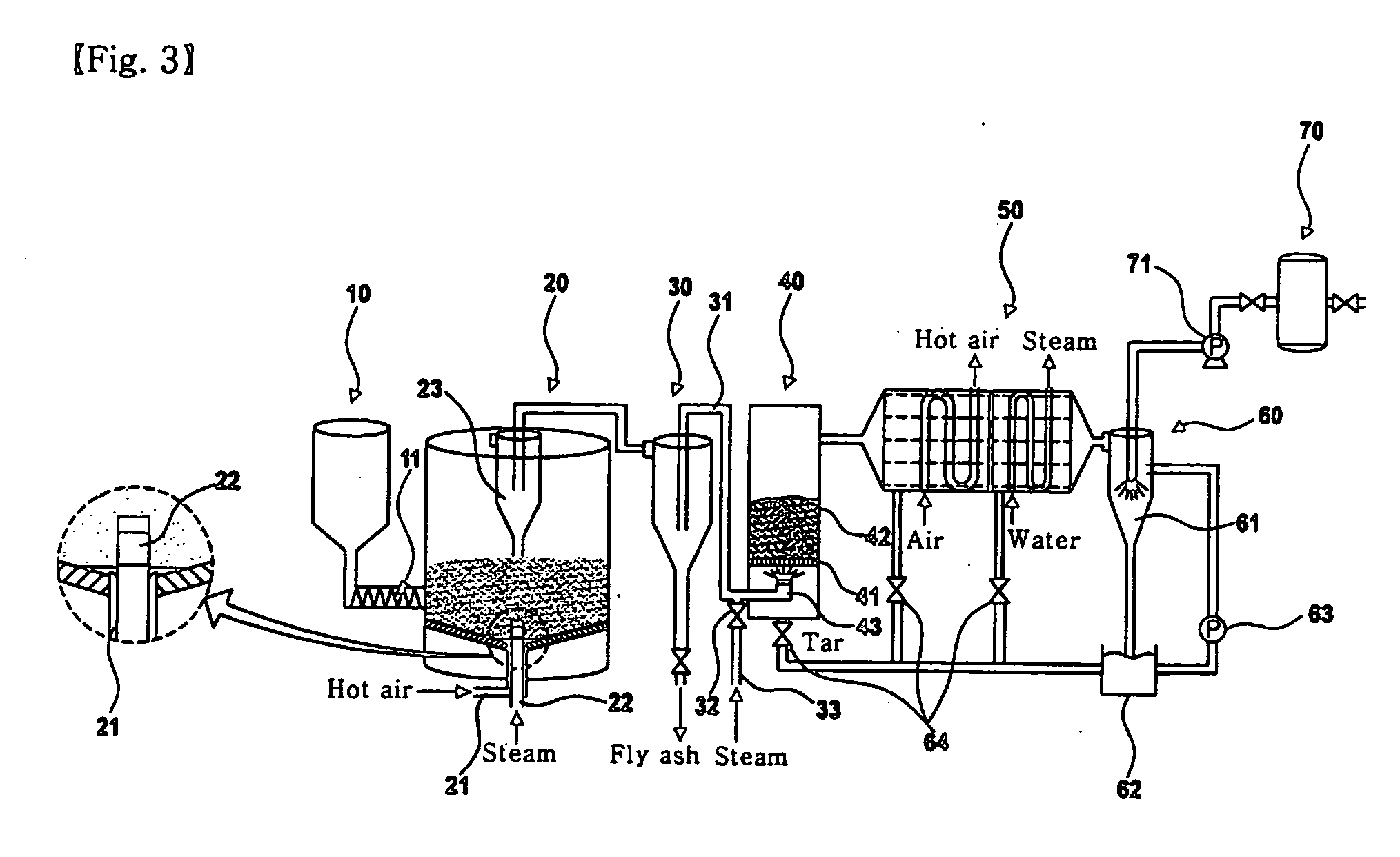
[0034] The gasification adopts a fluidized-bed type which may be driven at a relatively low temperature. Thus, even if the gasification is conducted at 850° C. using inexpensive coarse limestone powders or particles which enable gasification at a low temperature, it may exhibit the same effects as conventional gasification at 1100° C. or more in the absence of a catalyst.
[0035] Conventionally, the reformation temperature of a tar reformer is in the range of 1200° C. or more, which is higher than a gasification temperature. However, in the present apparatus, the reformation temperature is decreased to 650° C. or less, and thus, the reformer of the present invention does not need an additional heat source. Before the catalytic reformation, hydrogen sulfide and phosphorous pentoxide gas acting as a catalyst poison component are fixed to be removed by the use of caustic lime, thus increasing the reformation of tar and the conversion of fuel-N into NH3 in the presence of a catalyst.
[0036] Although tar, regarded as an unnecessary material, is re-circulated or wasted in a conventional process, in the present invention, unreacted tar, tar generated from the catalytic reformation, and a liquid product formed upon cooling the gas are recovered and then used for other purposes. Typically, additional devices or usage methods are required to re-introduce an undesired liquid component such as tar caused by a conventional coal gasification process into the gasification process or to use it as a liquid fuel. However, in the present invention, since such a component may be used as an agglomerating agent to form an agglomerate, it is not problematic.

Problems solved by technology

Generally, although gasification is used to maximally convert solid fuel into gas fuel, it may be limitedly applied in a partial gasification process.
Since the gasification of coal is typically performed at a high temperature, it requires a lot of energy.
Consequently, the system is too large or is complicated.
Further, a pure oxygen or air separating device for the production of a gas having high caloric value is used, thereby increasing the driving cost or mounting cost.
Hence, the partial oxidation in the absence of a catalyst is disadvantageous because high-temperature air or enriched oxygen must be used to achieve high-temperature gasification.
Further, expensive heat resistant material suitable for high-temperature reactions should be used, and also, the reactor has a short service life.
Furthermore, about 2˜5% of the free carbon that is produced by high-temperature partial combustion using a fixed-bed reactor is deposited, and the reaction efficiency is gradually decreased, thus requiring additional cost for removing the deposited material.
However, the above gasification is limited to use for waste containing a higher ash content or catalytic poison.
However, since these catalysts have low activities due to catalytic poison at a low temperature, they may need to undergo high-temperature reaction or reproduction to be stably used.
For example, an Ni catalyst reacts at high temperature with alumina, to produce NiAl2O4, resulting in decreased catalytic activity.
The catalyst used is expensive precious metal, and is thus recovered using a gas-liquid separator to be reused.
A solid-solid catalytic reaction is difficult to perform in practice.
However, a complicated apparatus for melting the remaining ash is necessary due to its low conversion.
To this end, however, accurate driving is required due to a complicated reactor and process.
The above apparatus is disadvantageous because first-stage pyrolysis is conducted at 450˜850° C., which is not high, in the absence of a catalyst, in consideration of high-temperature volatilization of heavy metal, thus obtaining a low gasification yield and generating excess tar.
Although exhaust flue gas desulfurization is considered for biomass containing a low sulfur content, pollution attributed to high content of phosphorous or fuel-N is not considered, causing secondary environmental pollution.

Method used


Image

  • Apparatus of catalytic gasification for refined biomass fuel at low temperature and the method thereof
  • Apparatus of catalytic gasification for refined biomass fuel at low temperature and the method thereof
  • Apparatus of catalytic gasification for refined biomass fuel at low temperature and the method thereof

Examples


example 1

Improvement Of Gas Generation Efficiency BY Catalytic Gasification

[0069] For gasification of SOCA (Sludge-Oil-Coal Agglomerates) in the presence of a catalyst mixture comprising Fe2O3 and CaO, the catalyst mixture and SOCA were uniformly mixed at a weight ratio of 3.4:1 under operation conditions similar to gasification in the absence of a catalyst, thus obtaining a gas product. The state of the product is shown in FIG. 4. The gasification in the presence of the catalyst mixture was initiated at 230° C., which was considerably lower than 560° C. required for gasification in the absence of a catalyst. In addition, compared to gasification in the absence of a catalyst, CO conversion was lower, and more hydrocarbons were generated. In particular, almost all hydrocarbons generated were confirmed to be methane gas. In the gasification in the absence of a catalyst, hydrocarbons were generated at 850° C. or more, and CO was generated at 1050° C. or more. However, when using a catalyst mix...

example 2

Less Generation Of Tar and Fuel-N Pollutant By Two-Stage Catalytic Gasification

[0070] As shown in FIG. 5, when a CaO catalyst, which is an oxide of an alkali earth metal, was used in the first stage gasification and an NiO catalyst was used in the second stage catalytic reformation, CO was similarly generated but a slightly larger amount of hydrocarbon was generated, compared to gasification using only CaO as the first stage catalyst Thereby, the reaction was completed in a shorter time. However, as is apparent from Table 1 below, in the case where calcium oxide was used as a first stage catalyst and NiO or MnO2 was used as a second stage catalyst, the generation of tar, NH3 and HCN was remarkably lower than when using only a first stage catalyst. It was considered that tar was reformed and fuel-N was converted into N2. In addition, the MnO2 catalyst was inferior in tar reformation to the NiO catalyst, by which fuel-N was converted not into ammonia but into HCN. Thus, the NiO catal...


PUM

PropertyMeasurementUnit
Temperatureaaaaaaaaaa
Volumeaaaaaaaaaa

Abstract

Disclosed is a gasification technique for converting biomass, which is difficult to treat, into clean gas fuel able to be burned in a cogeneration system. The gasification technique includes first stage fluidized-bed catalytic gasification, and second stage gasification of tar and catalytic reforming to convert nitrogen in tar, and HCN in a flammable gas into NH3, unlike conventional gasification techniques. In addition, since the temperature of a total gasification process is lower than a melting point of ash, powdery ash is generated and thus easily treated. Also, little heat is released due to the low process temperature, and therefore, a compact reactor may be designed to produce gas having a high caloric value. Further, the generated tar is recovered and reused in other processes, and the gas fuel contains a small amount of ammonia.

Description

TECHNICAL FIELD [0001] The present invention relates, in general, to gasification techniques for using biomass having a low inorganic ash content and a high nitrogen content as clean fuel in a local heating system of a big city. [0002] In particular, the present invention relates to an apparatus and method for manufacturing a gas fuel via clean gasification of a selectively refined mixture (SOCA: Sludge-Oil-Coal Agglomerates) comprising biomass organic waste, heavy oil, and coal. [0003] As such, the gas fuel obtained after clean gasification is a clean gas fuel usable in gas combustors, such as gas engines, gas turbines, vapor turbine generators, fuel cells, boilers, etc., or in heating devices. In addition, the biomass is organic solid materials, which include industrial waste such as sewage sludge, pulp sludge, etc., living waste such as home waste, excretions, etc., agricultural waste, livestock excretions, or wood chips. BACKGROUND ART [0004] Generally, gasification techniques h...

Claims


Application Information

Patent Timeline
IPC IPC(8): C10L3/00
CPCB01J23/02B01J23/34B01J23/745B01J23/75B01J23/78B01J37/04C01B2203/0272C10J3/54C10J3/56C10J2200/158C10J2300/0916C10J2300/093C10J2300/0946C10J2300/0956C10J2300/0973C10J2300/0983C10J2300/0989C10J2300/1846C10J2300/1869C10J2300/1884C10J2300/1892C10K1/024C10K1/046C10K1/18C10K1/20C10J3/482C10J3/84C10K1/026C10K1/08C10K3/02C10K3/023C10J2300/1693Y02P20/52C10G1/00
Inventor KANG, SUNG-KYUSHIN, HYUN-DONG
Owner KOREA INST OF ENERGY RES
Learn More