
Junction temperature prediction method and apparatus for use in a power conversion module

a power conversion module and junction temperature prediction technology, applied in the direction of instruments, nuclear elements, heat measurement, etc., can solve the problems of inability to measure the temperature of a diode or igbt junction directly, inaccurate conventional prediction methods described above, and failure of devices, so as to increase the accuracy of junction temperature prediction algorithm and accurately predict the junction temperature of switching devices

Active Publication Date: 2007-03-29
ROCKWELL AUTOMATION TECH
View PDF1 Cites 44 Cited by
  • Summary
  • Abstract
  • Description
  • Claims
  • Application Information

AI Technical Summary

Benefits of technology

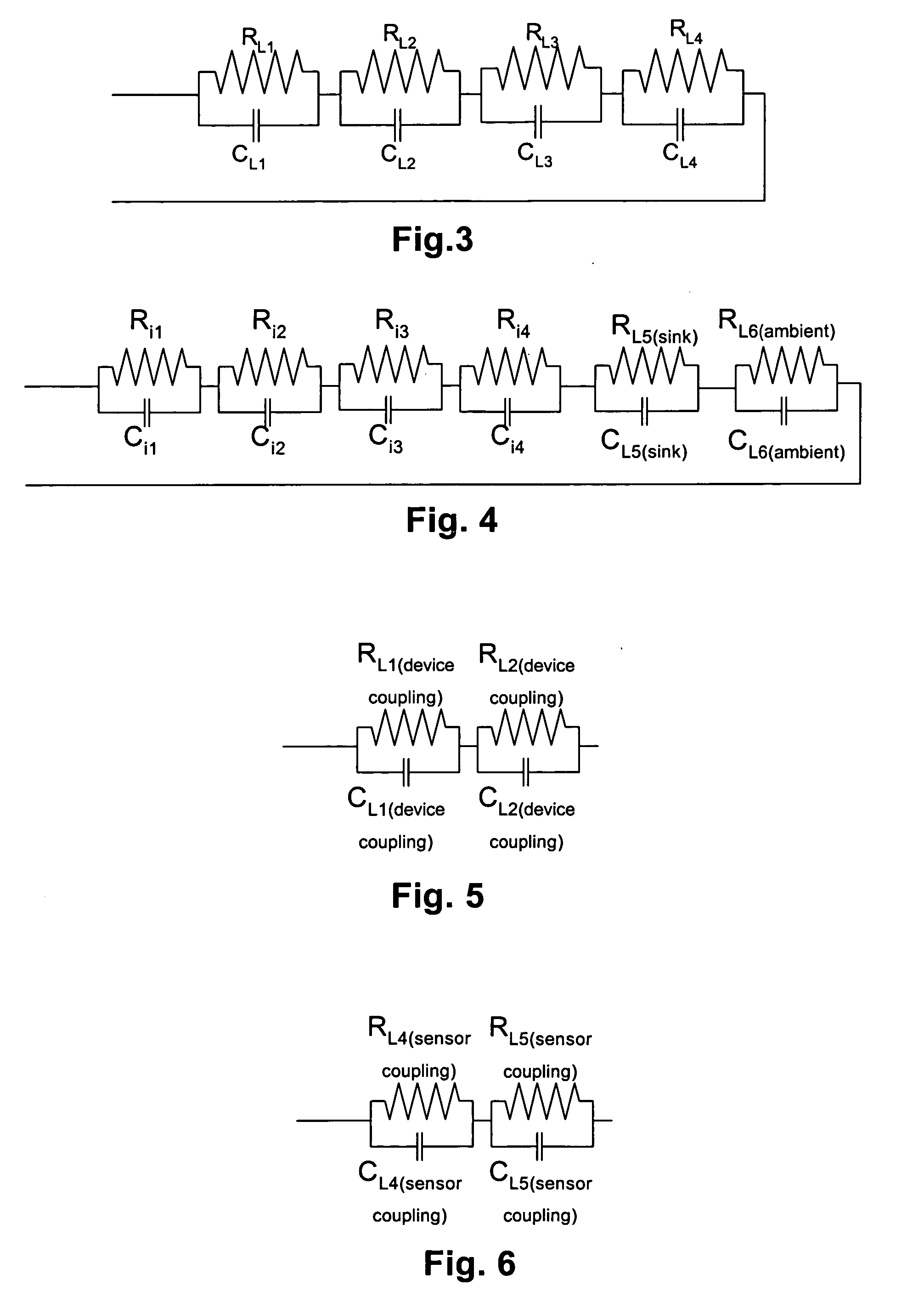
[0009] It has been recognized that the accuracy of a junction temperature prediction algorithm can be increased substantially by accounting for the effects of at least some inter-module switching device heating as well as the effects of other ambient heating characteristics. Thus, the present invention includes methods and apparatus that relatively accurately predict switching device junction temperature by accounting for at least a subset of heating characteristics of adjacent devices and at least a subset of module impedances.

Problems solved by technology

When IGBT or diode junction temperature exceeds a specific threshold temperature associated with a device type, the devices have been known to fail.
It is not possible to measure the temperature of a diode or IGBT junction directly and therefore device junction temperature has to be estimated or predicted.
Unfortunately, when devices are mounted in close formations on a single heat sink, the conventional prediction method described above has been shown to be inaccurate.
In the case of tightly packed devices on a single sink, because one device is extremely close to other devices on the sink, heat form one device tends to heat up adjacent devices.
For instance, in at least some experiments it has been observed that under DC conditions in a six-pack IGBT inverter module, a maximum prediction error of nearly 30 degrees Celsius has occurred when using th conventional prediction method.
While this solution substantially eliminates the failure problem, this solution is relatively expensive as circuits including larger and more costly switching devices are required for specific current levels and switching frequencies.
In addition, because the switching devices are physically larger, the sinks for mounting the devices are larger and the overall space required to accommodate the conversion modules is increased.

Method used


Image

  • Junction temperature prediction method and apparatus for use in a power conversion module
  • Junction temperature prediction method and apparatus for use in a power conversion module
  • Junction temperature prediction method and apparatus for use in a power conversion module

Examples


Embodiment Construction

[0036] Development of the Temperature Predicting Model

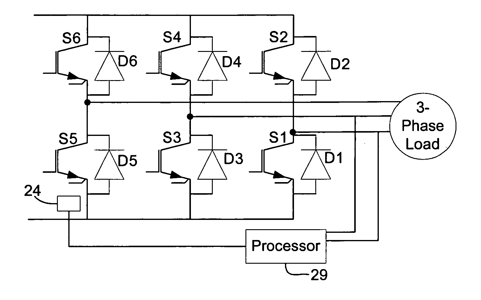
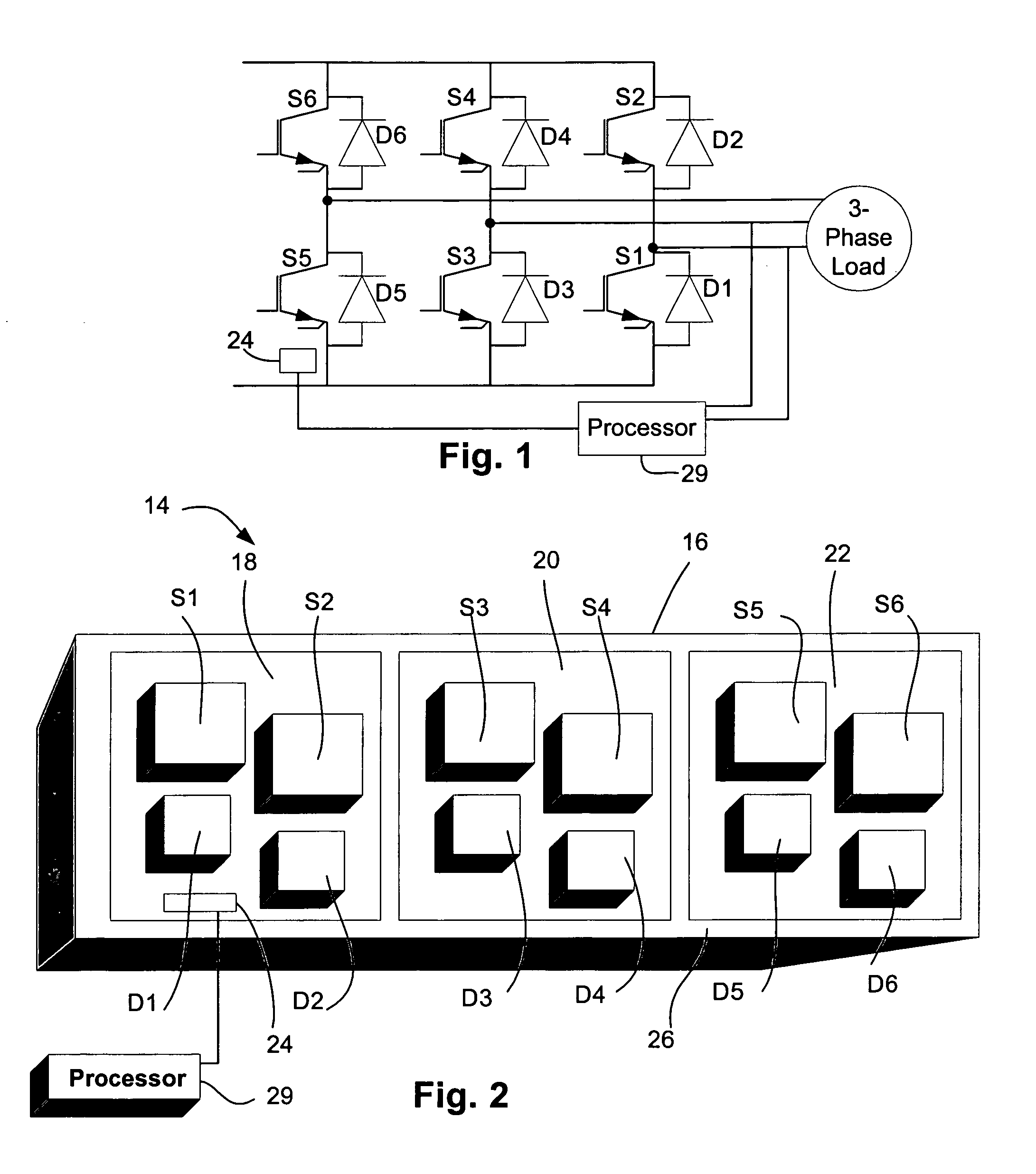
[0037] Referring now to the drawings wherein like reference numerals correspond to similar elements throughout the several views and more specifically, referring to FIG. 1, the present invention will be described in the context of an exemplary three phase DC to AC inverter type power conditioning module 10. Module 10 includes six IGBT switch devices S1-S6 and six diodes (also generally referred to as switching devices) D1-D6, a separate diode linked to each of the IGBTs in inverse parallel relationship. The IGBT switches are linked in series pairs across positive and negative DC buses and a central node of each pair is linked to a separate phase of a three phase load 12 (e.g., motor). As known in the power conversion art, by switching the IGBTs, three phase voltage delivered to load 12 can be controlled.

[0038] Referring still to FIG. 1, current sensors 23 are linked to the motor supply lines for, as the label implies, sensing l...


PUM


Abstract

A method and apparatus for predicting junction device temperature of at least a first switching device in a power conversion module that includes the first switching device and at least a second switching device, the method comprising the steps of identifying a cross thermal impedance value indicative of how the temperature of the second switching device effects the first switching device temperature an using the cross thermal impedance value to predict the temperature of the at least a first switching device.

Description

CROSS-REFERENCE TO RELATED APPLICATIONS [0001] Not applicable. STATEMENT REGARDING FEDERALLY SPONSORED RESEARCH OR DEVELOPMENT [0002] Not applicable. BACKGROUND OF THE INVENTION [0003] The present invention relates to integrated gate bipolar transistor (IGBT) modules and more specifically to a method and apparatus for predicting the junction temperatures of IGBTs in an IGBT module operating at a low frequency or a DC condition. [0004] Because of their advantageous operating characteristics (e.g., high switching speeds) IGBTs are used in many different types of power conditioning modules including AC to DC converters, DC to AC inverters, AC-DC-AC converters, etc. For example, in the case of a DC-AC inverter, six IGBTs are arranged to form an inverter bridge along with six diodes. [0005] During switching operations IGBTs and diodes generate heat that has a magnitude related to the switching frequency as well as the amount of current passing through the devices. When IGBT or diode junc...

Claims


Application Information

Patent Timeline
IPC IPC(8): G01K1/00G01K3/00G01K11/00
CPCG01K7/425H02M7/00H02M1/32
Inventor KERKMAN, RUSSEL J.WEI, LIXIANGLUKASZEWSKI, RICHARD A.BROWN, BRIAN P.GOLLHARDT, NEILWEISS, BRUCE W.
Owner ROCKWELL AUTOMATION TECH
Learn More