
Production of nanostructures by curie point induction heating

a nanostructure and curie point technology, applied in the direction of electric/magnetic/electromagnetic heating, physical/chemical process catalysts, metal/metal-oxide/metal-hydroxide catalysts, etc., can solve the problem of tight control of reaction temperature, the size of a susceptor that can be used, and the temperature gradient along the length of the oven

Inactive Publication Date: 2007-03-29
THE BOARD OF TRUSTEES OF THE UNIV OF ARKANSAS +1
View PDF6 Cites 25 Cited by
  • Summary
  • Abstract
  • Description
  • Claims
  • Application Information

AI Technical Summary

Benefits of technology

[0016] The method also includes the steps of supplying a feedstock reagent to the reaction zone, heating the susceptor to increase the temperature of the susceptor to the Curie temperature, and keeping the susceptor substantially at the Curie temperature for a period of time for the growth of desired nanostructures from the catalyst and the feedstock reagent. In one embodiment, the heating step includes the step of inductively heating the susceptor with an electromagnetic field with an RF.
[0017] The method may further include the step of optimizing the characteristic temperature for the growth of the desired nanostructures. The optimizing step comprises the step of selecting the ferromagnetic material with a Curie temperature that substantially corresponds to a temperature at which the growth of the desired nanostructures occurs. The method may also include the step of maintaining a sufficient amount of the feedstock reagent in the reaction zone.
[0018] In a further aspect, the present invention relates to a method for synthesizing nanostructures. In one embodiment, the method includes the steps of providing a susceptor containing a catalyst, where the susceptor is made of a ferromagnetic material having a characteristic temperature, and heating the susceptor substantially at the characteristic temperature for the growth of desired nanostructures from the catalyst. The heating step comprises the steps of inductively heating the susceptor to increase temperature of the susceptor to the characteristic temperature, and keeping the susceptor substa

Problems solved by technology

One of the major limitations of a conventional CCVD nanostructure reactor for nanostructure synthesis is the size of a susceptor that can be used.
Large size susceptors, desirable for producing large quantities of carbon nanostructures, introduce difficulties in controlling the hydrocarbon gas flow over the catalyst powder bed and attaining tight control of a reaction temperature.
Furthermore, the use of conventional ovens results in temperature gradient along the length of the oven.
This temperature gradient results in varying temperature conditions that have a significant negative impact on the quality, characteristics, and purity of carbon nanostructures grown therein.
Additionally, conventional ovens consume large amounts of energy and heat inefficiently.
Susceptor mass becomes an increasingly important synthesis bottleneck as one attempts to scale up for large scale production.
Therefore, a heretofore unaddressed need exists in the art to address the aforementioned deficiencies and inadequacies.

Method used


Image

  • Production of nanostructures by curie point induction heating
  • Production of nanostructures by curie point induction heating
  • Production of nanostructures by curie point induction heating

Examples


Embodiment Construction

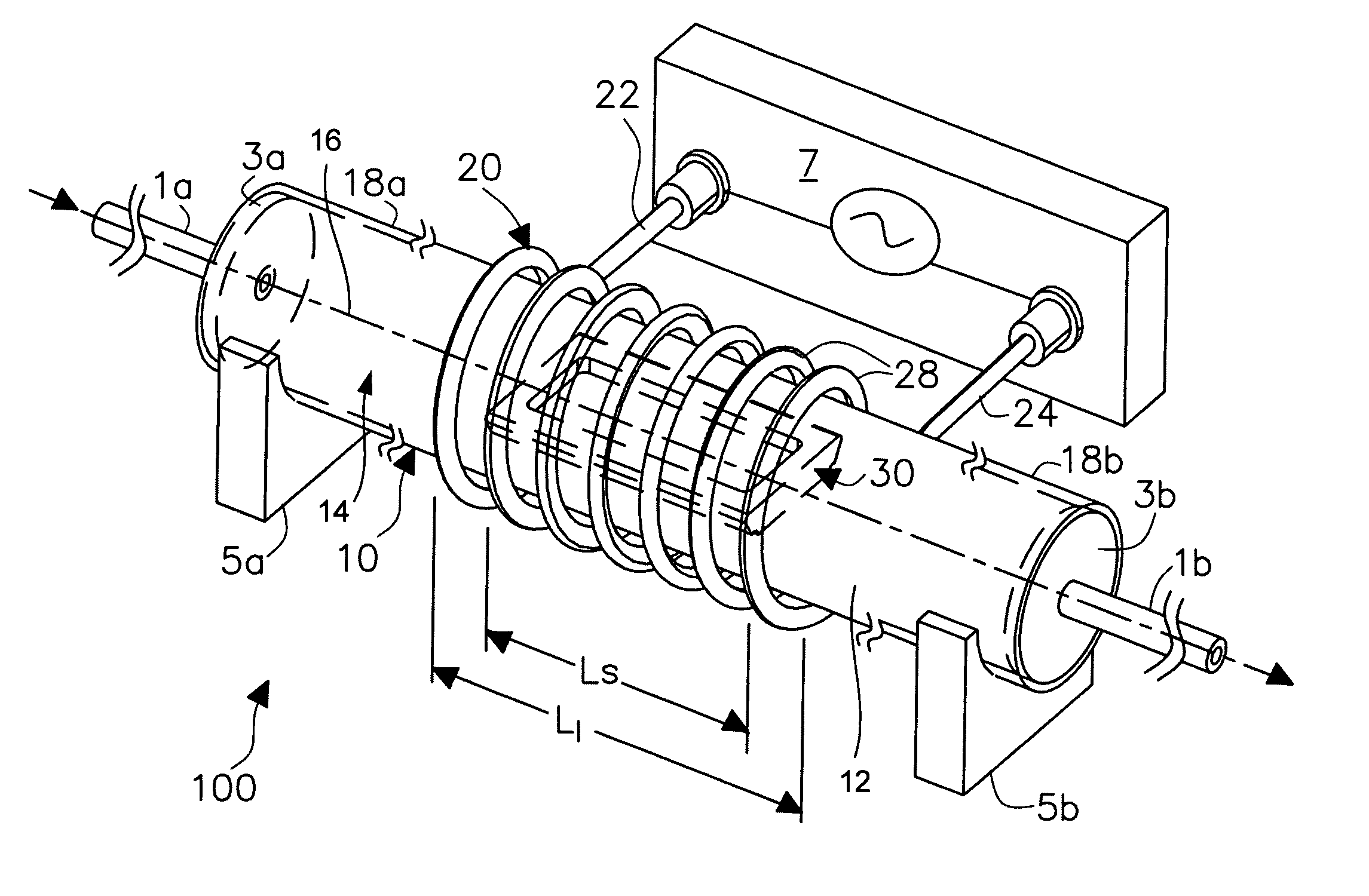
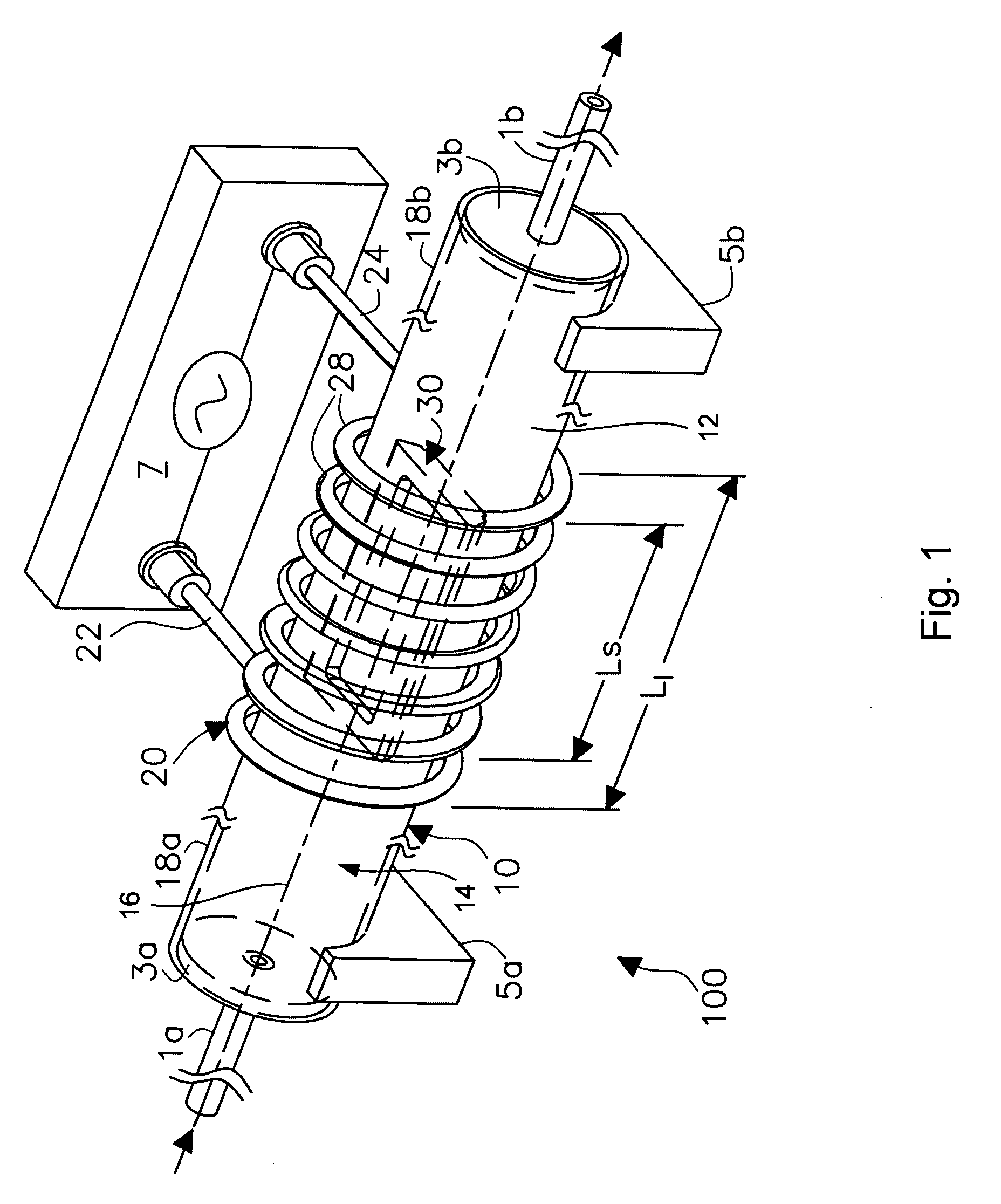
[0027] The present invention is more particularly described in the following examples that are intended as illustrative only since numerous modifications and variations therein will be apparent to those skilled in the art. Various embodiments of the invention are now described in detail. Referring to the drawings FIGS. 1-5, like numbers indicate like components throughout the views. As used in the description herein and throughout the claims that follow, the meaning of “a”, “an”, and “the” includes plural reference unless the context clearly dictates otherwise. Also, as used in the description herein and throughout the claims that follow, the meaning of “in” includes “in” and “on” unless the context clearly dictates otherwise. Moreover, titles or subtitles may be used in the specification for the convenience of a reader, which shall have no influence on the scope of the present invention. Additionally, some terms used in this specification are more specifically defined below.

Defini...


PUM

PropertyMeasurementUnit
Temperatureaaaaaaaaaa
Electrical conductivityaaaaaaaaaa
Currentaaaaaaaaaa

Abstract

An apparatus for synthesizing nanostructures. In one embodiment, the apparatus includes a heating device that defines a reaction zone therein and a susceptor made of a ferromagnetic material with a Curie temperature and placed in the reaction zone, where the Curie temperature substantially corresponds to a temperature at which the growth of desired nanostructures occurs and the heating device is capable of heating the susceptor substantially at the Curie temperature.

Description

CROSS-REFERENCE TO RELATED PATENT APPLICATION [0001] This application is a continuation-in-part of U.S. patent application Ser. No. 11 / 228,023, filed Sep. 15, 2005, entitled “APPARATUS AND METHODS FOR SYNTHESIS OF LARGE SIZE BATCHES OF CARBON NANOSTRUCTURES,” by Alexandru Sorin Biris, Alexandru Radu Biris, Dan Lupu, Jon Gardner Wilkes, Dan Alexander Buzatu, Dwight Wayne Miller, and Jerry A. Darsey (hereinafter the “'023 application”), the disclosure of which is hereby incorporated herein by reference in its entirety. The status of the '023 application is pending and itself claims the benefit, pursuant to 35 U.S.C. § 119(e), of U.S. provisional patent application Ser. No. 60 / 611,018, filed Sep. 17, 2004, entitled “APPARATUS AND METHODS FOR SYNTHESIS OF LARGE SIZE BATCHES OF CARBON NANOSTRUCTURES,” by Alexandru Sorin Biris, Dan Alexander Buzatu, Alexandru Radu Biris, Jon Gardner Wilkes, Dwight Wayne Miller, Jerry A. Darsey, and Dan Lupu. The '023 application also is a continuation-in-...

Claims


Application Information

Patent Timeline
IPC IPC(8): H05B6/10
CPCB01J8/0015Y10T117/10B01J8/087B01J8/12B01J8/1836B01J8/1845B01J8/40B01J12/007B01J23/44B01J23/755B01J23/88B01J2208/00469B01J2208/00557B01J2208/0084B82Y30/00B82Y40/00C01B31/0233C23C16/46H05B6/108H05B2206/023Y10S977/90Y10S977/844B01J8/0285C01B32/162
Inventor WILKES, JON GARDNERBUZATU, DAN ALEXANDERMILLER, DWIGHT WAYNEBIRIS, ALEXANDRU SORINBIRIS, ALEXANDRU RADULUPU, DAN M.DARSEY, JERRY A.
Owner THE BOARD OF TRUSTEES OF THE UNIV OF ARKANSAS
Learn More