
Method and system for intrusion prevention and deflection

a technology applied in the field of intrusion prevention and deflection techniques, can solve the problems of inability to address, make recognition impossible, and the effectiveness of the detection system to los

Active Publication Date: 2007-03-15
TELECOM ITALIA SPA
View PDF17 Cites 89 Cited by
  • Summary
  • Abstract
  • Description
  • Claims
  • Application Information

AI Technical Summary

Benefits of technology

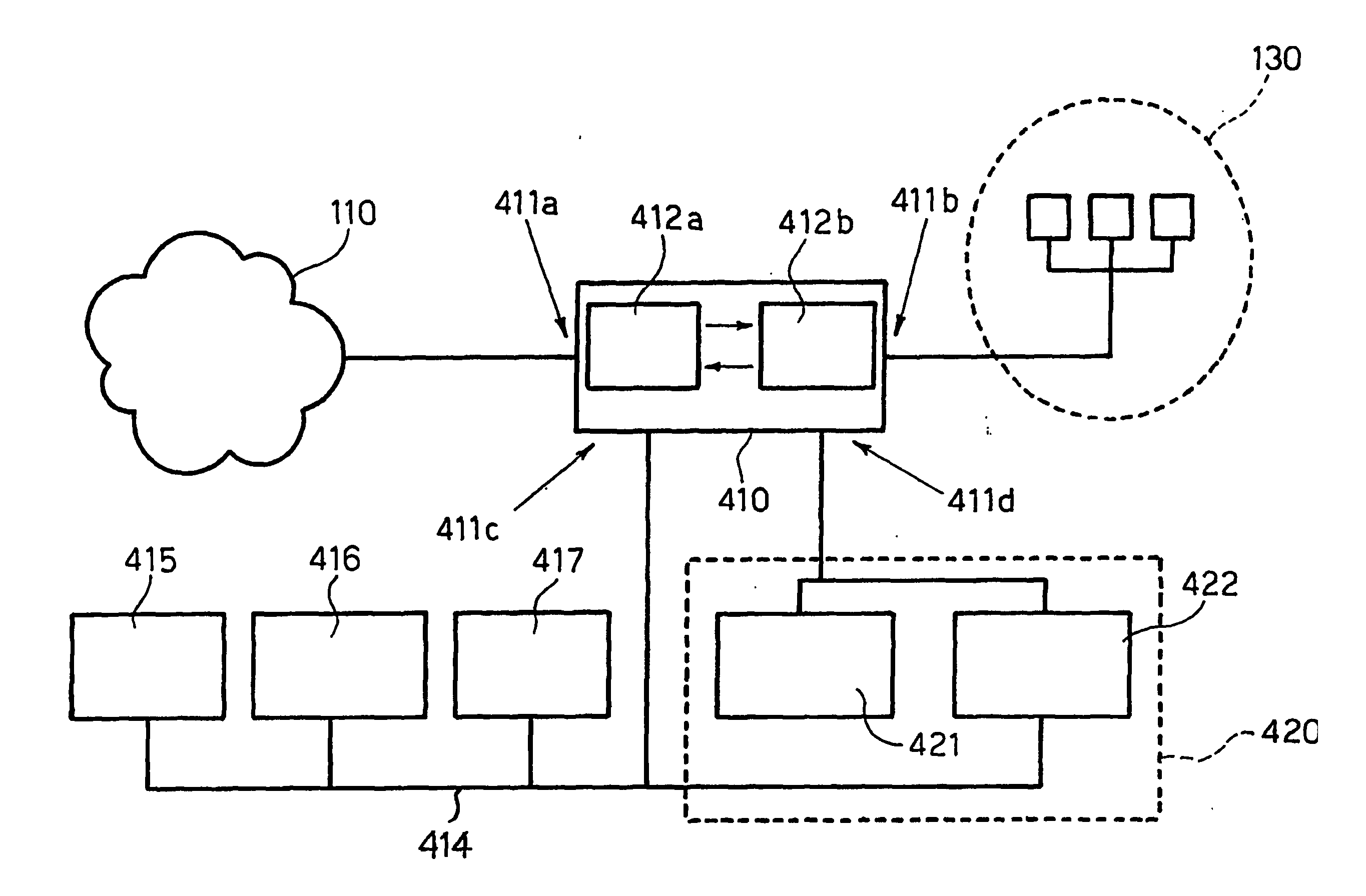
[0053] A preferred embodiment of the invention therefore prevents intrusion in communication traffic with a set of machines in a network, the traffic comprising communication entities identified by respective patterns. A test system including test facilities replicating at least one of the machines in the set is provided and at least a part of the communication entities in said traffic are directed towards the test system, where they are run on the test facilities to detect possibly adverse effects on the test system. In the presence of an adverse effect, the communication entities leading to the adverse effect are blocked. In the absence of an adverse effect, communication with the set of machines protected is allowed for the communication entities failing to lead to an adverse effect.
[0059] To sum up, the arrangement described herein provides an architecture which maintains the advantages of all the arrangements of the prior art, while dispensing with the intrinsic drawbacks of those intrusion detection systems (of the network-based type) having insufficient knowledge available of the final systems. The arrangement described herein also avoids the intrinsic invasive nature of a host-based intrusion detection system, while ensuring that potentially dangerous traffic is blocked and not allowed to propagate to the protected machines.

Problems solved by technology

Otherwise, the detection system will lose its effectiveness.
The signatures in question usually include an attack pattern: therefore, even a relatively minor change in the pattern makes recognition impossible.
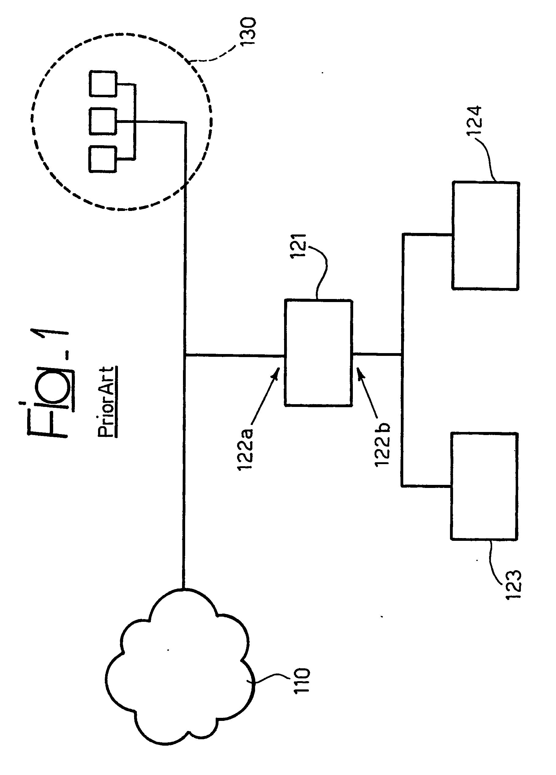
The monitoring interface is not provided with an IP address, and therefore cannot be addressed.
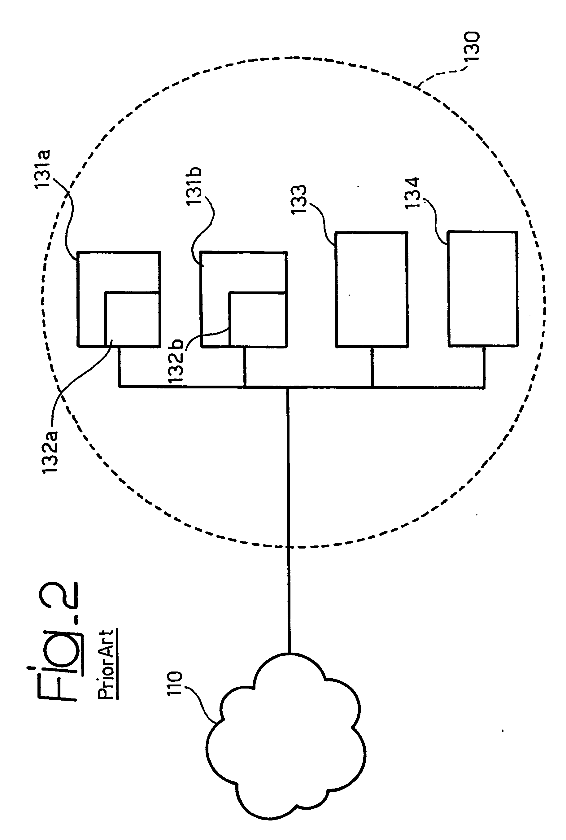
The main disadvantage of such a network-based IDS lies in that it does not have a precise knowledge of the status (services offered, software used, actual vulnerability, and so on) of the machines coming down to the network segment 130 being controlled.
The system activity is limited to monitoring traffic by searching for attack pattern, without knowing whether these represent an actual threat for the systems to be protected.
This entails a reduced effectiveness in detection and increases in the number of false alarms.
Any time an attack pattern is detected, such a system issues an alarm, having typically a variable degree of seriousness depending on the attack type.
This approach produces a huge amount of signalling (in a large network, a single sensor may generate one thousand such alarms per day), thus making it very difficult, if not impossible, to manage such a tool.
Additionally, a good deal of the alarms are in fact false alarms: in fact, the network sensor does not operate in an intelligent manner and issues alarms also when the dangerous packet is addressed to a non-existing machine (this being a typical situation generated by tools adapted for automatically generating attacks) or when the machine is not vulnerable to a given attack, because it does not provide a specific service or is equipped with an updated and protected software release.
This situation leads to handling huge amounts of largely irrelevant data, which may be however be reported with a high degree of gravity, with the risk of however somehow hiding real alarms and diverting time and resources from the task of tackling with actual problems.
In fact, if the intrusion detection and the end-system to which the data are addressed are exposed to different traffic flows, the risk exists that an attack may be unobserved by the detection system, while reaching the final target.
The same time problems arise when the need exists of re-constructing TCP (Transmission Control Protocol) level data flows.
Re-transmission makes re-construction of the traffic flow by an intrusion detection system more complex, in that a packet being re-sent is intercepted by the IDS more than once.
A network-based intrusion detection system has in fact no warranty and no way for discovering whether a given packet has been accepted or dispensed by the end system being monitored.
Again, insertion phenomena (the IDS accepts and considers as valid packets that are dispensed with by the end-system) and evasion (the IDS does not take into account packets that are accepted by the end-system) result in a strong limitation in the detection effectiveness of the systems.
In brief, the basic problem making a network-based IDS vulnerable to insertion and evasion lies in that the IDS and the end-system may in certain contexts be exposed to two different data flows as they are separate machines, with distinct operating systems and implementations of the TCP / IP stack.
This limitation and the drawbacks referred in the foregoing do limit the detection capability of a network-based IDS and essentially derive from the reduced knowledge available to the intrusion detection system in respect of the status and configuration (operating system, software used, services offered, actual vulnerability and so on) of the machines coming down to the network segment being controlled.
Being directly hosted on the system controlled a host-based system (HIDS) system is open to attacks and runs the risk of being disabled as is the case for any other programs running on the same machine.
The basic limitation of such a system is consequently related to its highly invasive character.
This may lead to a reduction of performance in the machine or, even worst, to conflict with other applications already installed.
This issue becomes even more critical when “production” machines are considered offering critical services, whose configuration can not be modified in order to avoid the risk of making them unstable.
Such a technique must be implemented in such a way to be fast: if the system does not react promptly, it may not be able to block the dangerous traffic flow or may finally intervene when the damage has already occurred.
One simply has to think of an attack whose dangerous content is limited to a single packet: this is a limit case where a counter-measure as described is totally useless.
However, this technique may not be exempt from the same limitations affecting the other techniques considered in the foregoing.
It is effective in the case of attacks exploiting a shell obtained by means of an exploit (in which case the exploit is executed, but the shell obtained is no longer reachable), but it turns out to be useless in the case of those attacks, such as denial-of-service (DOS) attacks, which exhaust their contents in few packets, or even just one packet.
An intrinsic limitation of these techniques is that they are not prevention techniques, in that they do not act before the packet reaches the target.
However, even the arrangement shown in FIG. 3 still suffers from the drawbacks described in the foregoing and related, as is the case of network-based systems, to the lack of precise knowledge of the status of the machines coming down to the network segment 130 being controlled.
In fact, also the arrangement shown in FIG. 3 limits its intervention to monitoring traffic while searching for attack patterns, without however knowing whether this may represent an actual threat for the systems protected.

Method used


Image

  • Method and system for intrusion prevention and deflection
  • Method and system for intrusion prevention and deflection
  • Method and system for intrusion prevention and deflection

Examples


Embodiment Construction

[0064] As previously indicated, the exemplary arrangement described herein provides network protection through the joined action of the two basic components, namely a network component that collects and analyzes the network traffic via an inner-line element, and a component that, even though different from the final machines, operates at a local level.

[0065] In most instances the servers to be protected are production machines whose configurations are not adapted to be modified, and wherein new software components are not suitable to be installed in order to avoid service instability.

[0066] The arrangement described herein therefore creates a test ambience wherein the services and the configurations of the machines in the internal network are replicated. The test ambience permits the effect of any potential dangerous communication entity (e.g. a packet) to be tested before this actually reaches the real service. In the case the packet is found to be a good one, it is re-directed t...


PUM


Abstract

A system for preventing intrusion in communication traffic with a set of machines in a network includes a data base having stored therein patterns representative of forbidden communication entities as well a firewall module configured for blocking forbidden communication entities in the traffic as identified by respective patterns included in the data base. The system also has another data base having stored therein patterns representative of allowed communication entities for communication with the set of machines and a test system including test facilities replicating the machines in the set. A communication module is configured for allowing communication of allowed communication entities as identified by respective patterns included in the other data base. Unknown communication entities as identified by respective unknown patterns not included in either of the data base and further data base are directed to the test system and run on the test facilities therein to detect possible adverse effects of such unknown communication entities on the test system. The system is further configured so that in the presence of an adverse effect, the unknown communication entity leading to the adverse effect is blocked by the firewall module, and in the absence of an adverse effect, communication of the unknown communication entity failing to lead to the adverse effect is allowed.

Description

FIELD OF THE INVENTION [0001] The present invention relates to techniques for intrusion prevention and deflection. [0002] The invention was devised by paying specific attention to the possible application in ensuring security of telecommunication networks. DESCRIPTION OF THE RELATED ART [0003] Typically two types of intrusion detection systems exist at present. [0004] A former type (usually referred to as a network intrusion detection system or network-IDS) essentially monitors traffic on a given network segment; a latter type (oftentimes referred to as a host-IDS) is adapted for monitoring events occurring on a specific system). [0005] Both systems analyze data while searching for attacks or policy violation acts. This is done by exploiting the knowledge and recognition algorithms available in order to emit a signal or an alarm when a match is found. Both approaches have advantages and drawbacks. [0006] Exemplary of a network-IDS is the arrangement disclosed in US-A-6 279 113. [000...

Claims


Application Information

Patent Timeline
IPC IPC(8): H04L12/26H04J1/16H04L29/06
CPCH04L12/2602H04L63/1408H04L63/02H04L43/00
Inventor BRUSOTTI, STEFANOCODA ZABETTA, FRANCESCO
Owner TELECOM ITALIA SPA
Learn More