
Diffusion sheet

a technology of diffusion sheet and diffusion plate, applied in the field of diffusion sheet, can solve the problems of unevenness or decrease in forward brightness, decrease in utilization efficiency, and decrease in light utilization efficiency, and achieve the effects of uniform and enhanced forward brightness, efficient reflection, and enhanced light utilization efficiency

Inactive Publication Date: 2007-03-08
FUJIFILM CORP +1
View PDF0 Cites 7 Cited by
  • Summary
  • Abstract
  • Description
  • Claims
  • Application Information

AI Technical Summary

Benefits of technology

The present invention provides a diffusion sheet that can efficiently reflect feedback light when the light has returned from the prism sheet to enhance the utilization efficiency of light and achieve uniform and enhanced forward brightness. The diffusion sheet includes a light reflection unit that reflects the feedback light toward the prism sheet again, and the fine projection section of the light reflection unit can be regularly or irregularly arranged to prevent occurrence of moire. The diffusion sheet can be used in a display device to improve image quality.

Problems solved by technology

Specifically, the light returning toward the diffusion sheet and the light guide plate upon reflection by the prism lenses, in its present form, is absorbed or becomes stray light, to thus become useless and result in decreased utilization efficiency of light.
From the viewpoint of an improvement in brightness, which is the purpose of use of the prism sheet, a decrease in utilization efficiency of light is not preferable, and results in unevenness or a decrease in forward brightness.

Method used


Image

  • Diffusion sheet
  • Diffusion sheet
  • Diffusion sheet

Examples


second embodiment

[0044] the diffusion sheet of the present invention will now be described.

[0045]FIG. 6 is a cross-sectional view of a diffusion sheet having a pad layer according to a second embodiment. FIG. 7 is a schematic diagram for describing operation of the diffusion sheet illustrated in FIG. 6. In the following embodiment, those members and locations which are the same as those illustrated in FIGS. 1 through 4, are assigned the same reference numerals, and their repeated explanations are omitted.

[0046] In the diffusion sheet 200, light reflection unit 41 has a pad layer 43 having an irregular structure formed on the surface of the translucent substrate 29 for diffusing light; and a light transmissive reflection layer 47 which is formed along the irregular structure of the pad layer 43 and which includes light diffusion-and-reflection fine particles 45 at predetermined density.

[0047] The pad layer 43 is formed on one surface of the translucent substrate 29 opposing the first prism sheet 17...

third embodiment

[0051] Next, there will be described the diffusion sheet of the present invention.

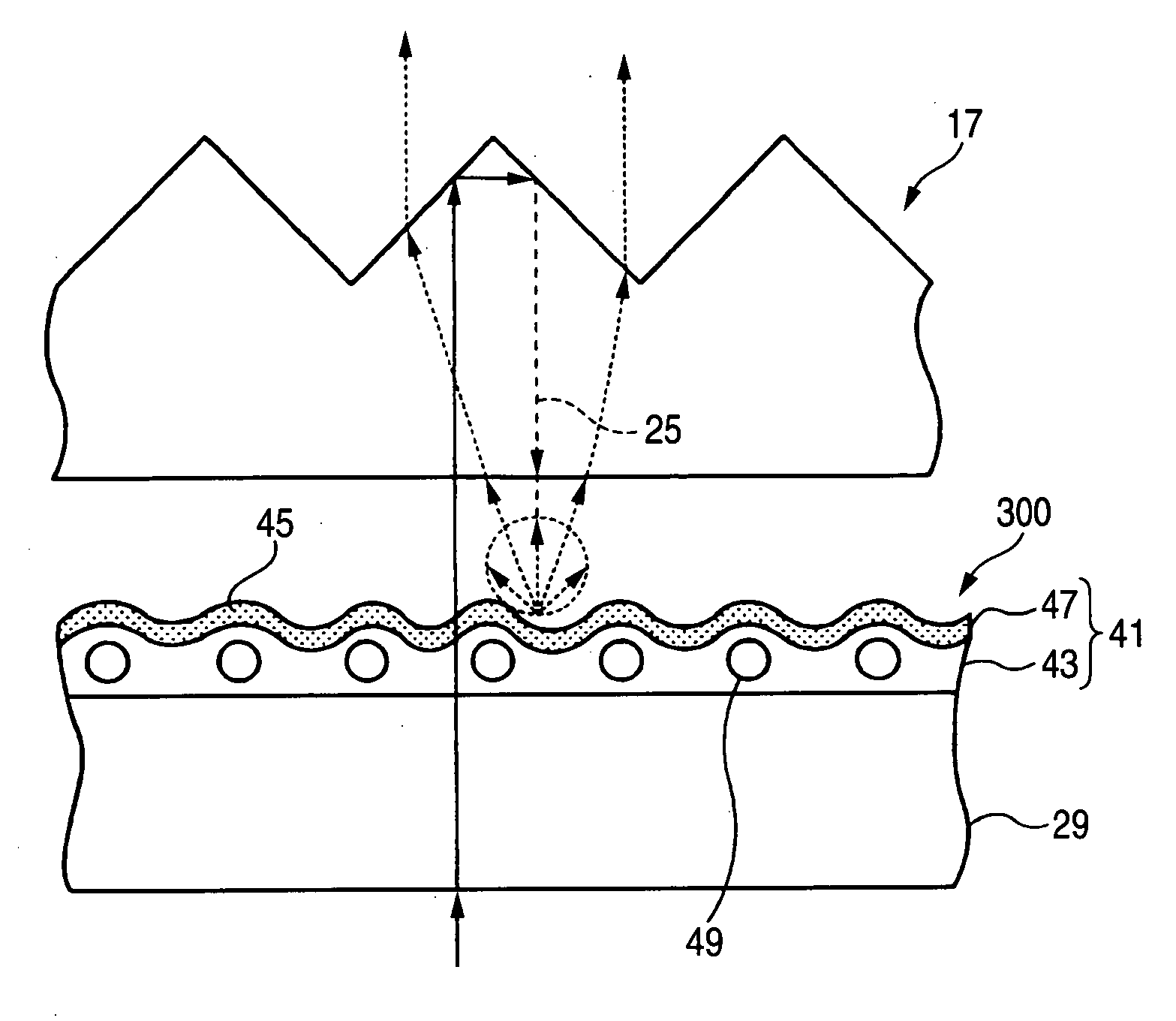
[0052]FIG. 8 is a cross-sectional view of the diffusion sheet of the second embodiment equipped with a light-gathering layer containing transparent fine particles; and FIG. 9 is a diagrammatic view for describing operation of the diffusion sheet illustrated in FIG. 8.

[0053] In the diffusion sheet 300, the light reflection unit 51 comprises a light-gather layer 55 which is formed on the surface of the translucent substrate 29 and contains transparent fine particles 53 for gathering transmitted light; and the light transmissive reflection layer 47 that is formed on the light exit surface of the light-gathering layer 55 and contains the light diffusion-and-reflection fine particles 45 at a predetermined density.

[0054] For instance, polymethylmethacrylate PMMA having high transparency is preferable as the transparent fine particles 53.

[0055] As illustrated in FIG. 9, in the diffusion sheet 300, the inci...


PUM


Abstract

A diffusion sheet interposed between a light guide plate and a prism sheet includes: a light reflection unit reflecting a feedback light toward the prism sheet again, the feedback light being returned by the prism sheet.

Description

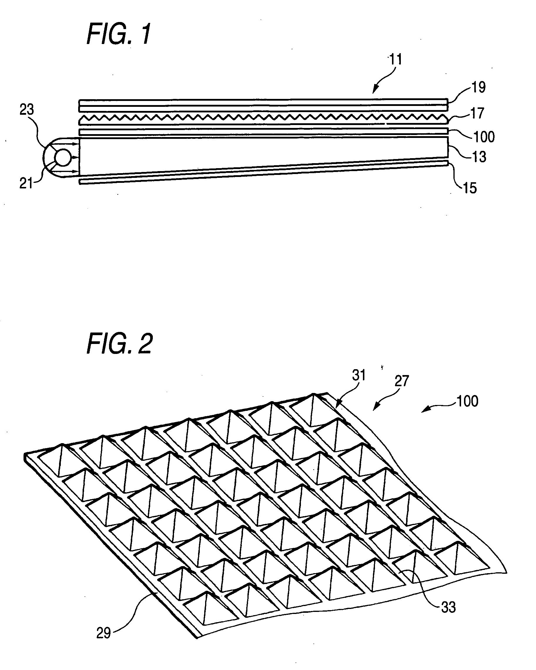
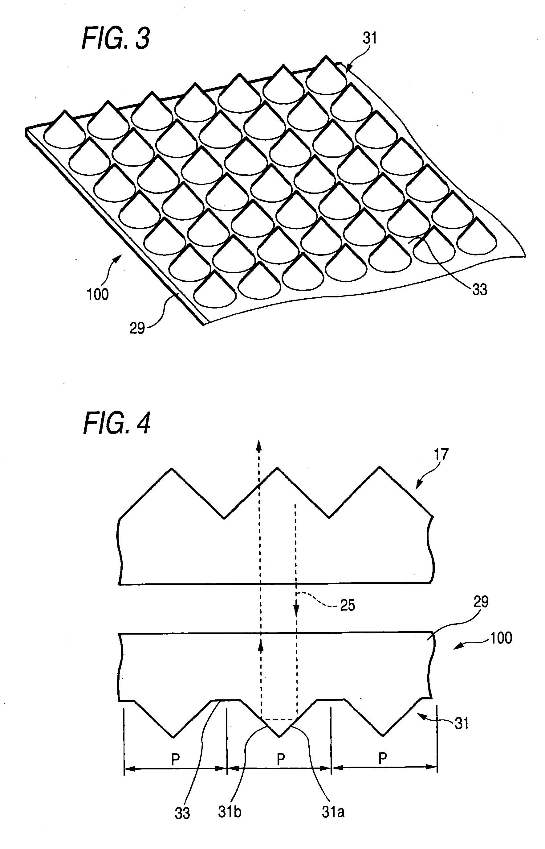
BACKGROUND OF THE INVENTION [0001] 1. Field of the Invention [0002] The present invention relates to a diffusion sheet for use in a display device of a flat-type TV, a cellular telephone, a digital camera, a car navigation system, a desktop PC, a mobile PC, a PDA, a cash dispenser, and the like. [0003] 2. Background Art [0004] In a display device, such as a liquid-crystal display device, brightness is improved by means of enhancing utilization efficiency of light. To this end, a diffusion sheet is placed on a light guide plate of a backlight unit, and one to two sheets of gable-like prisms are additionally placed on the diffusion sheet. The prisms on the surface of the prism sheet gather light within a plane orthogonal to a crest of each of the prisms. In the backlight unit using the prism sheets, the light guide plate is stacked on the diffusion sheet and a reflection sheet, and another prism sheet is provided at a light exit side of the diffusion sheet. The backlight is housed in ...

Claims


Application Information

Patent Timeline
Patent Type & Authority Applications(United States)
IPC IPC(8): G02B5/02
CPCG02B5/0221G02B5/0226G02B5/0231G02B6/0053G02B5/045G02B6/0051G02B5/0278
Inventor NAGAO, KIMITOSHI
Owner FUJIFILM CORP
Learn More