
Single-lip drill and method for the production thereof

a single-lip drill and drill bit technology, applied in the direction of turning tools, boring/drilling tools, reaming tools, etc., can solve the problem of ecological objection to large coolant quantities

Active Publication Date: 2007-02-22
TBT TIEFBOHRTECHN
View PDF19 Cites 10 Cited by
  • Summary
  • Abstract
  • Description
  • Claims
  • Application Information

AI Technical Summary

Benefits of technology

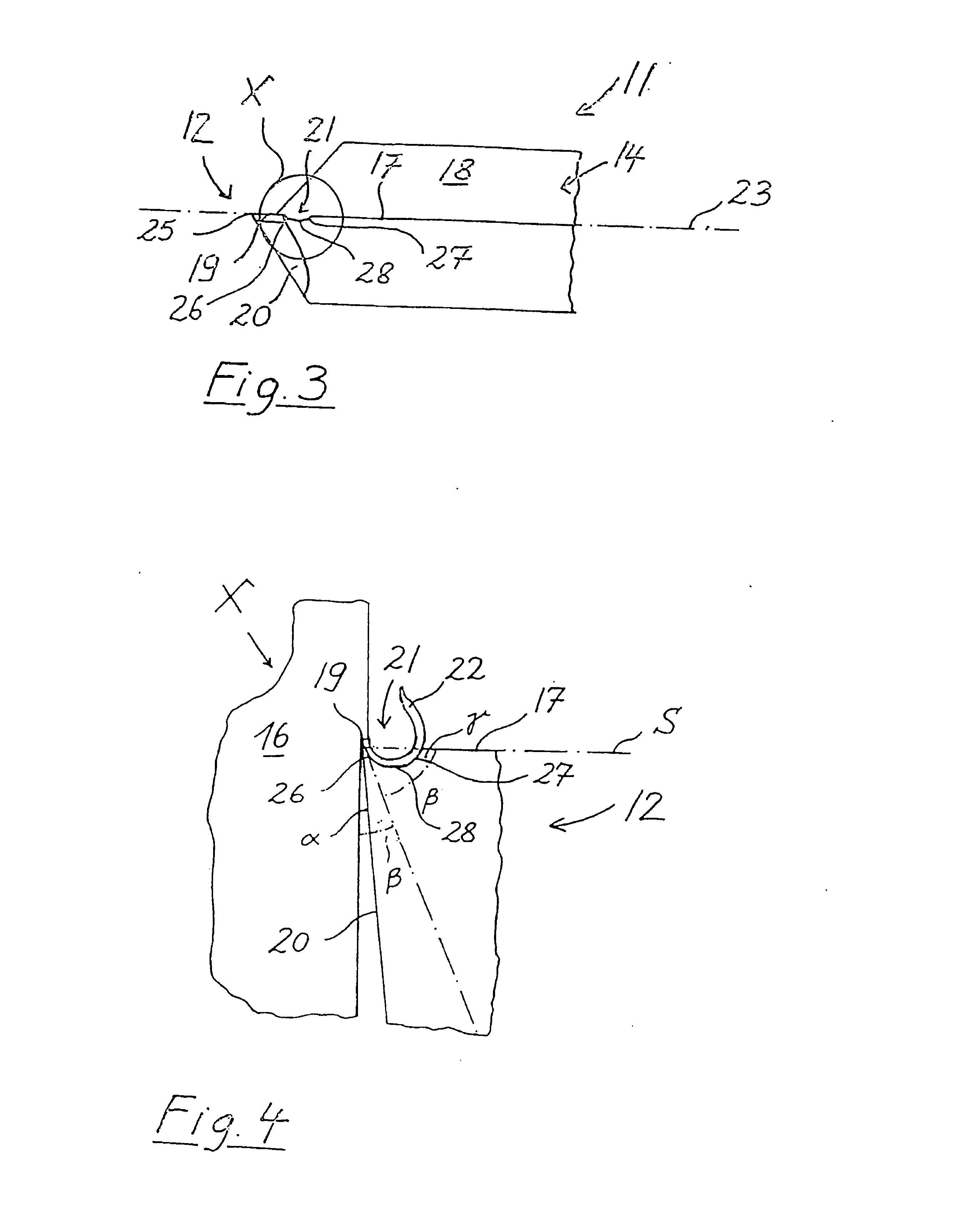
[0008] The positive rake angle on the chip former of the inventive single-lip drill ensures that unlike in the case of e.g. conventional single-lip drills with a 0° rake angle, the cut off chip no longer feeds against the tool face at right angles, but instead in sloping manner, because the tool face is inclined with respect to the imaginary line perpendicular to the machining surface. Thus, on meeting the tool face the chips are less strongly compressed, so that the loading of the tool face produced by the impinging chips and which can e.g. lead to heat evolution due to the friction between chips and workpiece, is relatively limited. Thus, a so-called “soft” cut is produced. Thus, the single-lip drill according to the invention can be used in production-reliable manner with minimum quantity lubrication, e.g. with compressed air or when using coolants having a low viscosity.
[0009] A further advantage of the single-lip drill according to the invention is that a planned chip shaping of the cut off chips is possible and can be adapted to minimum quantity lubrication conditions. For reliable chip removal by the coolant, it is firstly necessary for the chips not to exceed a given size, because otherwise they would not be reliably carried along through the limited space within the corrugation. This can lead to the chips collecting in the vicinity of the bit, so as to impede the drilling process. In the case of conventional single-lip drills with a rake angle of 0, the problem of a long-breaking chip does not normally arise, because as a result of the strong chip compression on the tool face usually a short-breaking chip is formed. However, extremely short chips are also not reliably removed when using coolants with a low viscosity, because they do not offer an adequate resistance. As a result of a chip breaker with a positive rake angle chips are formed which are small enough to be reliably moved and on the other large enough to offer low viscosity coolants an adequate removal application surface.
[0013] In particularly preferred manner the chip break section is located at a distance from the cutting edge suitable for setting a desired chip size. This allows a planned chip size setting of the cut off chip. By varying the distance between the chip break section and the cutting edge it is possible to produce chips with a different size and shape, which are adapted in optimum manner to the given coolant conditions, particularly to minimum quantity lubrication conditions, i.e. can be reliably removed.
[0020] One function of the functional coating is to increase the wear resistance of the drill, particularly at high cutting speeds. As a result of the functional coating abrasion of the single-lip drill on contact with the workpiece to be worked, particularly in the vicinity of the cutting edge, is reduced. In addition, there is a prevention of cratering, which can arise when chips slide on the chip former and chip out material from the structure of the latter. Another advantage of the functional coating is that adhesion between the single-lip drill and the workpiece to be worked is reduced. It in particular prevents, especially at high pressure levels between the single-lip drill and the workpiece, a welding together of the workpiece material and the bit known as a “built-up cutting edge”.

Problems solved by technology

The use of large coolant quantities is ecologically objectionable, because the coolant-chip mixture constitutes waste material, which must be disposed of or reprocessed.
However, despite the limited coolant quantity, a problem is to ensure an adequate chip removal in order to ensure a good deep drilling process quality.

Method used


Image

  • Single-lip drill and method for the production thereof
  • Single-lip drill and method for the production thereof
  • Single-lip drill and method for the production thereof

Examples


Embodiment Construction

[0035]FIG. 1 shows an embodiment of the single-lip drill according to the invention, merely showing the drill head 11. Single-lip drills essentially comprise a drill shank and a drill head 11 more particularly integrally joined to the shank, or a solid hard metal or carbide tool. The shank is joined to the drill head 11 preferably by a soldering process, e.g. by brazing. The drill shank is connected to a clamp collar, which is in turn fixed in a tool mounting of a single-lip deep drilling machine. The shank or the solid hard metal tool can be firmly connected, particularly integrally with the clamp collar, e.g. by an adhesive or soldered joint.

[0036] The single-lip drill together with the clamp collar is also referred to as a single-lip deep drilling tool.

[0037] The drill head 11 has a blade or bit 12 formed in the vicinity of the end face thereof, a cooling lubricant or coolant supply channel 13 in the interior of the drill head 11, a groove or corrugation 14 for removing the coo...


PUM

PropertyMeasurementUnit
diameteraaaaaaaaaa
diameteraaaaaaaaaa
diametersaaaaaaaaaa

Abstract

Disclosed is a single-lip drill comprising a drill head (11) that is provided with a blade (12) which is embodied on said drill head. The blade encompasses a cutting edge (19) for machining a workpiece (16) in a cutting manner. At least one chip-forming device (21) which shapes chips (22) cut by the cutting edge is associated with the cutting edge. The chip-forming device is provided with a positive cutting angle (gamma) such that the mechanical and thermal stress can be reduced in the area of the blade (12). In addition, the chip-forming device can comprise a functional coating (29a, 29b) which is made especially of hard material and is applied after providing the drill with the exterior shape thereof.

Description

FIELD OF USE AND PRIOR ART [0001] The invention relates to a single-lip drill and to a method for its manufacture. The single-lip drill has a drill head provided with a blade or bit. The bit has a cutting edge for the machining by cutting of a work-piece. With the cutting edge is associated at least one chip former for shaping the chips cut off by the cutting edge. [0002] Single-lip drills are standard drills used in deep drilling. Deep drilling is a cutting method for producing or making holes. Deep holes are normally those having a diameter between approximately 1 and 1500 mm and having a depth starting from approximately three times the diameter. Single-lip drilling is a special variant of deep drilling, where use is made of a single-lip drill. Single-lip drills can be subdivided into those with a bit ground on the tool and those having a replaceable bit, e.g. in the form of a cutting tip or reversible cutting tip. Single-lip deep drilling is preferably performed with diameters f...

Claims


Application Information

Patent Timeline
Patent Type & Authority Applications(United States)
IPC IPC(8): B23B51/00B23B51/04B23P15/28
CPCB23B51/0486B23B2224/24B23B2224/32B23B2226/31B23B2228/10B23B2251/04Y10T407/245B23B2251/48B23P15/28Y10T408/78Y10T408/9095Y10T408/909Y10T408/89B23B2251/424B23B51/066
Inventor RANDECKER, HERMANNBAUMGARTNER, HEINER
Owner TBT TIEFBOHRTECHN
Learn More