
Method for producing magnetic recording medium and magnetic recording medium

Inactive Publication Date: 2007-02-08
TDK CORPARATION
View PDF6 Cites 20 Cited by
  • Summary
  • Abstract
  • Description
  • Claims
  • Application Information

AI Technical Summary

Benefits of technology

[0010] In view of the foregoing problems, various exemplary embodiments of this invention provide a method for manufacturing a magnetic recording medium which enables efficient and ensured manufacture of a magnetic recording medium having a recording layer formed in a concavo-convex pattern and a satisfactorily flat surface, and a magnetic recording medium.
[0011] In the process of achieving the present invention, the inventors of the present invention tried to remove an excessive non-magnetic material above a recording layer by using ion beam etching so as to flatten the recording layer. Since the ion beam etching is likely to selectively etch away a protruding portion of a film prior to the other part, its flattening effect is high. Furthermore, the use of ion beam etching corresponding to a dry process instead of a wet process such as a CMP technique eliminates the need of cleaning a slurry and the like. Therefore, it is believed that a magnetic recording medium having a small surface roughness can be efficiently manufactured at a low cost.
[0013] In the ion beam etching, a projecting portion of a film is likely to be selectively etched away prior to the other part. However, if the projecting portion has a relatively large area, only the vicinity of periphery of the projecting part is etched away fast and the inner area is etched away slower than the periphery thereof. A magnetic recording medium is divided into a data region and a servo region for use. Although a concavo-convex pattern of a recording layer is generally simple in the data region, a concavo-convex pattern of the servo region remarkably differs from that of the data region. Moreover, the concavo-convex pattern of the recording layer often becomes complex in the servo region. Therefore, since a concavo-convex shape of the surface of the non-magnetic material does not have a simple pattern, an etching rate varies depending on the size of area of each projecting portions. Therefore, in spite of the use of ion beam etching, the effect of reducing the surface roughness has a certain limit.
[0014] Accordingly, as a result of further diligent examination, the inventors of the present invention achieved the present invention as follows. A material whose state is selectable between a flowing state and a cured state is deposited in a flowing state as a non-magnetic material on a surface of an object to be processed including a recording layer formed in a concavo-convex pattern over a substrate. A concave portion of the concavo-convex pattern is filled with the non-magnetic material to reduce the concavity and convexity of the surface of the non-magnetic material deposited following a concavo-convex shape of the recording layer. Specifically, even if the non-magnetic material has a concavo-convex surface shape following the concavo-convex pattern of the recording layer immediately after deposition, the concavity and convexity are gradually flattened as long as the non-magnetic material is in a flowing state. Therefore, the concavity and convexity of the surface of the non-magnetic material can be remarkably reduced at a stage prior to the flattening step. Furthermore, the concavity and convexity of the surface can be considerably reduced by the flattening that follows. It is preferable to employ dry etching such as ion beam etching for the flattening step.
[0032] In the present invention, a non-magnetic material is deposited in a flowing state, so that the concavity and convexity of the surface of the non-magnetic material can be satisfactorily flattened prior to flattening. Therefore, a surface roughness can be satisfactorily reduced to a desired level at the flattening step. As a result, a magnetic recording medium having a recording layer formed in a concavo-convex pattern and a satisfactorily flat surface can be efficiently and surely manufactured.

Problems solved by technology

However, although a certain effect of reducing the surface roughness can be obtained by using ion beam etching, it is still difficult to satisfactorily reduce the surface roughness to a desired level.
Moreover, the concavo-convex pattern of the recording layer often becomes complex in the servo region.
Therefore, in spite of the use of ion beam etching, the effect of reducing the surface roughness has a certain limit.

Method used


Image

  • Method for producing magnetic recording medium and magnetic recording medium
  • Method for producing magnetic recording medium and magnetic recording medium
  • Method for producing magnetic recording medium and magnetic recording medium

Examples


example 1

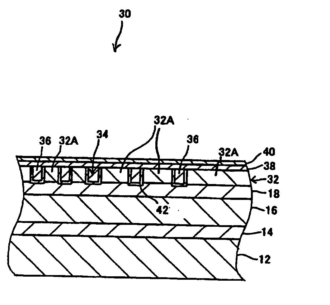
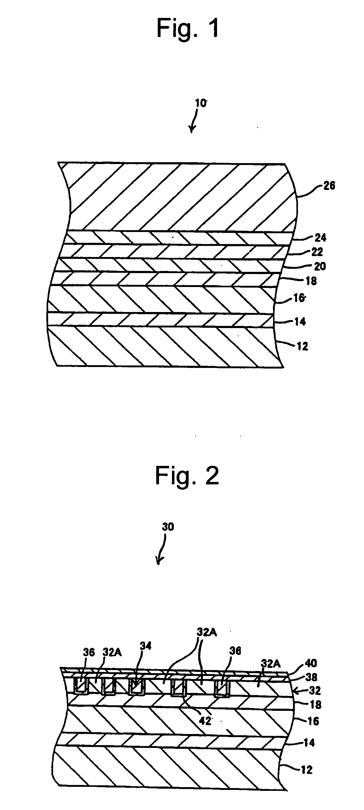
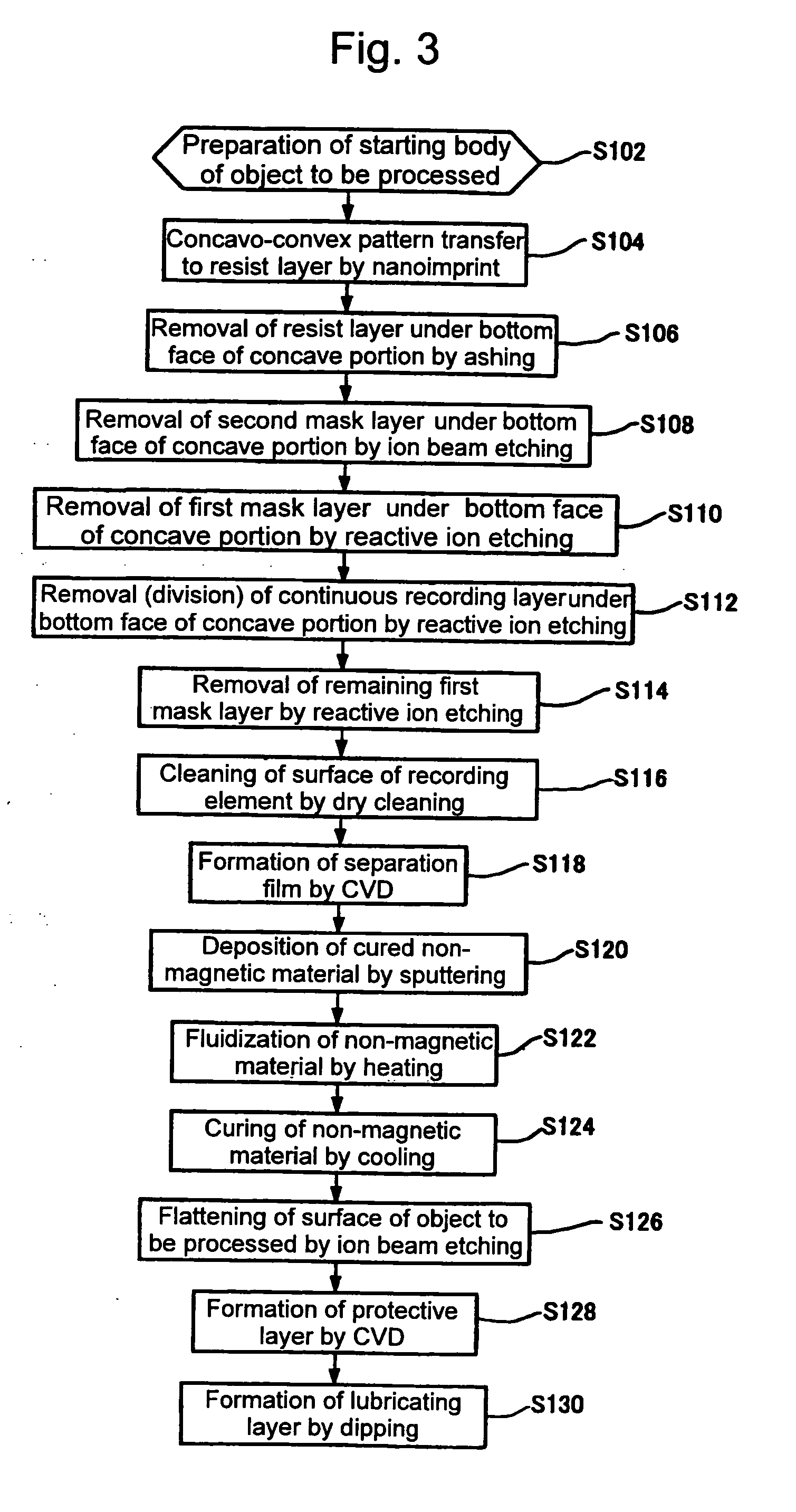
[0110] As described in the first exemplary embodiment above, ten magnetic recording media 30 were manufactured by using In as the non-magnetic material 36. Specifically, after In was deposited by sputtering on the surface of the object to be processed 10 including the recording layer 32 formed in a concavo-convex pattern over the substrate 12, the object to be processed 10 was kept and heated in a temperature environment at approximately 200° C. for approximately 5 minutes while being rotated so as to flatten the surface of In. Next, the object to be processed 10 was kept and cooled in a normal temperature environment with the addition of an extremely small amount of Si particles to the surface of In, thereby curing In. Then, Ar gas was radiated approximately perpendicularly to the surface of the object to be processed 10 so as to remove In until the surfaces of the recording elements 32A were exposed. In this manner, the surface of the object to be processed 10 was flattened. Furth...

example 2

[0111] In contrast with Example 1, ten magnetic recording media 30 were manufactured by using an ultraviolet curable resin as the non-magnetic material 36 in place of In. Specifically, after the ultraviolet curable resin was deposited by spin coating on the surface of the object to be processed 10 including the recording layer 32 formed in a concavo-convex pattern over the substrate 12, an ultraviolet ray was radiated onto the ultraviolet curable resin for approximately 5 minutes so as to cure it. Then, Ar gas was radiated approximately perpendicularly to the surface of the object to be processed 10 so as to remove the ultraviolet curable resin until the surfaces of the recording elements 32A were exposed. In this manner, the surface of the object to be processed 10 was flattened. The other conditions were set the same as those of Example 1 above. As a result of measurement of the largest level difference of the surface of each magnetic recording medium 30 obtained in the above-desc...

example 3

[0112] As described in the second exemplary embodiment above, ten magnetic recording media 30 were manufactured by using SiO2 as the non-magnetic material 37. Specifically, after SiO2 was deposited by sputtering on the surface of the object to be processed 10 including the recording layer 32 formed in a concavo-convex pattern over the substrate 12, the resist material was deposited by spin coating on the surface of SiO2 while the object to be processed 10 was being rotated. Next, Ar gas was radiated approximately perpendicularly to the surface of the object to be processed 10 so as to remove the resist material and SiO2 until the surfaces of the recording elements 32A were exposed. In this manner, the surface of the object to be processed 10 was flattened. The Ar gas was radiated without curing the resist material in a flowing state. Furthermore, the protective layer 38 and the lubricating layer 40 were formed to manufacture ten magnetic recording media 30. As a result of measuremen...


PUM


Abstract

A method for manufacturing a magnetic recording medium, which enables efficient and ensured manufacture of a magnetic recording medium having a recording layer formed in a concavo-convex pattern and a satisfactorily flat surface, and a magnetic recording medium are provided. According to the method for manufacturing a magnetic recording medium, a material whose state is selectable between a flowing state and a cured state is used as a non-magnetic material 36. After the non-magnetic material 36 is formed in a flowing state on a surface of an object to be processed 10 including a recording layer 32 formed in a concavo-convex pattern over a glass substrate 12, then the non-magnetic material 36 is cured.

Description

TECHNICAL FIELD [0001] The present invention relates to a method for manufacturing a magnetic recording medium including a recording layer formed in a concavo-convex pattern and a magnetic recording medium. BACKGROUND ART [0002] Conventionally, an areal density of a magnetic recording medium such as a hard disk is remarkably increased by improvement such as the miniaturization of magnetic particles forming a recording layer, the modification of a material, or the highly precision processing of head. The areal density is expected to be further increased in the future. [0003] However, problems such as the processing limit of a head, a side fringe due to expansion of a magnetic field, and a crosstalk become noticeable. As a result, the improvement of the areal density by a conventional technique for improvement reaches its limit. Therefore, as a potential magnetic recording medium enabling the realization of further improvement of the areal density, a discrete type magnetic recording m...

Claims


Application Information

Patent Timeline
IPC IPC(8): G11B5/65B05D5/12G11B5/84G11B5/855
CPCG11B5/855
Inventor OKAWA, SHUICHIHATTORI, KAZUHIROSUWA, TAKAHIROTAKAI, MITSURU
Owner TDK CORPARATION
Learn More