
Boat control system

a control system and boat technology, applied in the field of boat control system, can solve the problems of severe damage, long operating hours, and the scope of the main engine of the boat to accomplish, and achieve the effects of low trolling speed, long operating hours, and fuel efficiency

Inactive Publication Date: 2007-02-08
STALLINGS JAMES
View PDF27 Cites 10 Cited by
  • Summary
  • Abstract
  • Description
  • Claims
  • Application Information

AI Technical Summary

Benefits of technology

[0017] The advantages of operating the thruster system with water-cooled motors are significant. As a result, the boat control system of the present invention can be used to propel the boat for long periods at low speeds previously unattainable with the high horsepower main engine(s). Consequently, when trolling for fish, a separate, outboard trolling motor is no longer necessary. The boat control system thrusters can maintain low trolling speeds for long periods, so the need for a trolling motor is overcome.
[0018] The long operating hours attainable by the boat control system of the present invention provides another important advantage to the boat owner, viz., fuel efficiency. Very often, a relaxing day of boating consists mainly of very slow cruising around an attractive river or bay with family and friends. The main boat engine(s) can propel the boat slowly enough at very low revolutions per minute, but at the cost of very low fuel efficiency coupled with exhaust smoke and noise. The boat control system of the present invention overcomes that disadvantage when tied into the rechargeable battery bank of the boat. The desirable slow gentle speed can be achieved with only two or more thrusters on and the main engine(s) off. No fuel is consumed, and exhaust fumes and combustion noises are eliminated.
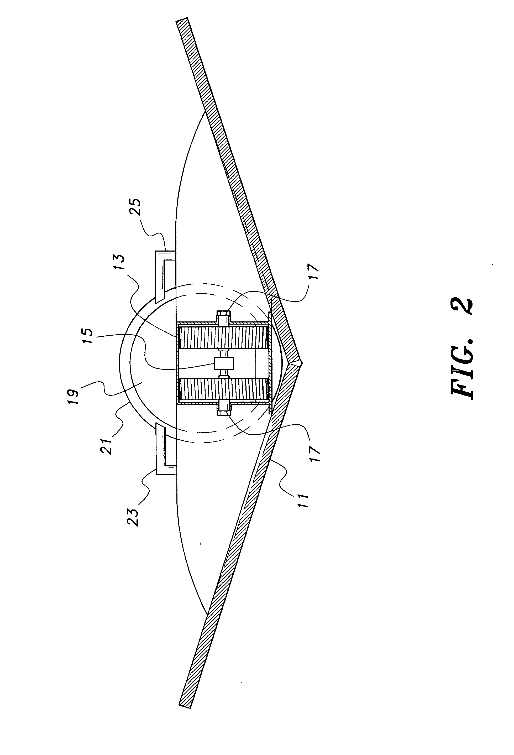
[0021] Other embodiments of the present boat control system place the thruster motors generally or substantially concentrically within the thruster duct, thereby obviating the need for an external drive shaft between the motor and the impeller shaft and its corresponding requirement for a dynamic seal. Moreover, ambient water flowing through the thruster duct during operation provides cooling for the motor within the duct without need for additional coolant lines and the like. Greater motor output, which results in greater heat output, also results in greater water flow through the duct to provide the cooling necessary.
[0024] Each of the three reversible, water-cooled DC electrical motors for the bow, stern and transom thruster installations is fully wired and connected to a battery bank and a thruster control joystick at the captain's wheel station. The instrumentation at the control joystick is known to those skilled in the art and allows the captain to select, start up and shut down any combination of thrusters for maneuvering the boat. Each independent pump is equipped with two impellers. Through the reversibility of the motor, the captain can select either the starboard or port side impeller to become engaged to discharge seawater through the selected thruster nozzle to turn the bow. In a similar manner, the stern thruster installation can be energized to operate either the port or starboard impeller to turn the boat's stern. If the captain prefers, both bow and stern thruster installation can be made operational simultaneously.

Problems solved by technology

Some of these maneuvers are well beyond the scope of the boat's main engine(s) to accomplish, particularly at very low speeds.
Thruster systems have heretofore typically not been placed in operation in open waters, for their usefulness in open waters requires long periods of operation compared to their operation in congested marinas and back waters.
Accordingly, protracted continuous operation of these thruster system motors in open water overheats the motors and causes severe damage.
However, it has been discovered that this drawback of previous thruster systems can be overcome by operating the thruster system with reversible direct current water-cooled electric motors.

Method used


Image

  • Boat control system
  • Boat control system
  • Boat control system

Examples


Embodiment Construction

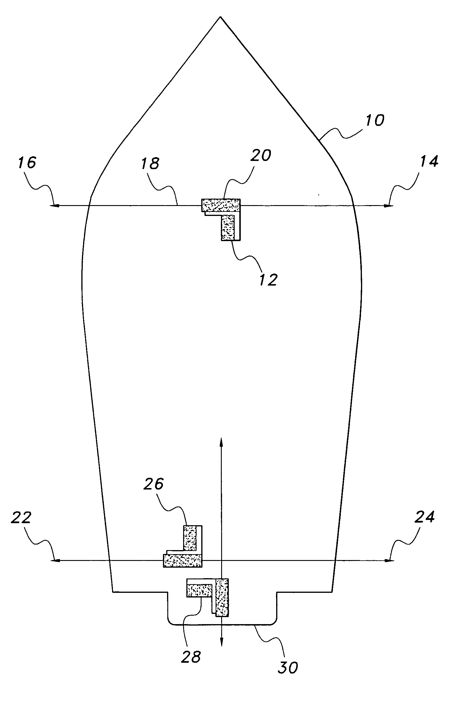
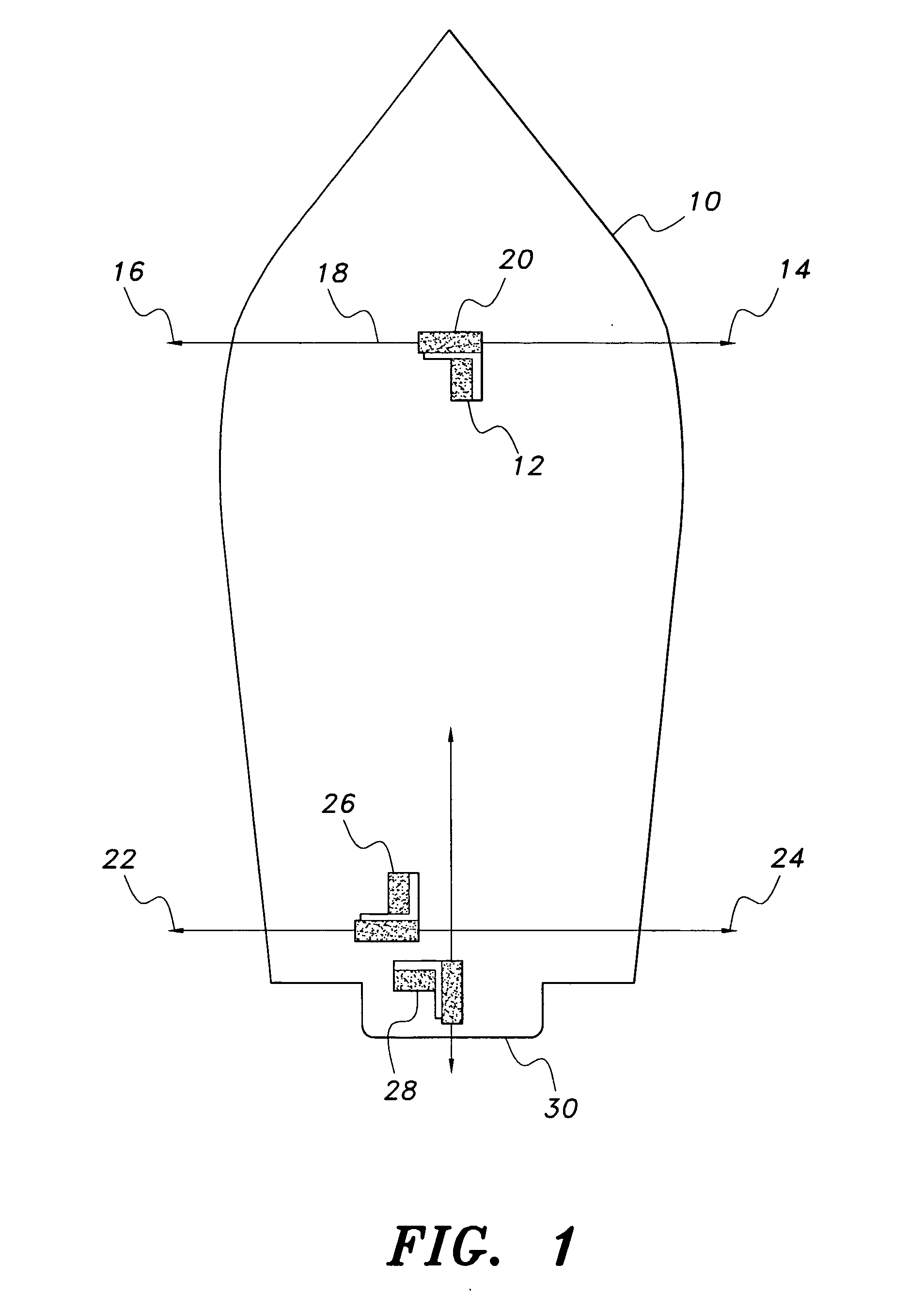
[0035] Referring to FIG. 1, a diagrammatic top view is presented showing the general shape of a boat 10. The bow thruster impeller pump 20 and reversible electric motor 12 are installed in the hull centered between the hull sides. The bow thruster nozzles 14 and 16 are connected to the pump 20 by flexible piping 18. The stern side lateral thrusters 22 and 24 and reversible electric motor and impeller pump 26 are installed in the hull close to the centerline of the hull. The forward and reverse unit, comprising the reversible electric motor and water impeller pump 28, is installed in the center line of the hull next to the transom 30, with one thruster nozzle installed on the stern and connected to the pump 28. The forward thruster nozzle is pointed obliquely down and to the rear into the seawater.

[0036] The system illustrated in FIG. 1 offers 360° thrust angles, including true straight lateral movement. The thruster units are controlled by one 3-axis joystick.

[0037] Referring to F...


PUM


Abstract

The boat control system is a propulsion system for controlling the direction of passage of a vessel underway at low speeds. Six thruster nozzles are installed around the hull so that, used individually or in combination, the boat can be maneuvered forward, backward, laterally or turned on its axis. Each impeller is driven by a water-cooled reversible DC electric motor, which allows the thruster apparatus to operate for long periods. In some embodiments, the motors are installed concentrically within their respective thruster ducts, with water flow through the ducts cooling the motors during operation. The system is controlled by a joystick located at the operator's station of the boat.

Description

REFERENCE TO RELATED PATENT APPLICATION [0001] This application is a continuation in part of U.S. patent application Ser. No. 11 / 135,410, filed on May 24, 2005.BACKGROUND OF THE INVENTION [0002] 1. Field of the Invention [0003] The invention disclosed herein relates to a propulsion system for controlling the direction of passage of a vessel underway at relatively low speeds without utilizing the power of the vessel's main engine(s). The invention particularly relates to a boat control system that includes at least one thruster installed in the bow or stern of a vessel, especially a power or a sail pleasure boat, that can selectively propel the craft forward, backward or laterally. The system's design allows the thruster apparatus to operate for long periods without overheating. [0004] 2. Description of the Related Art [0005] The use of thrusters as a means of enhancing the turning capability of a boat or ship is well known in the marine arts. When maneuvering to enter or exit a dock...

Claims


Application Information

Patent Timeline
Patent Type & Authority Applications(United States)
IPC IPC(8): B63H25/46
CPCB63H25/46B63H25/42
Inventor STALLINGS, JAMES
Owner STALLINGS JAMES
Learn More