
Torque-detecting device

a technology of torque detection and torque, which is applied in the direction of force sensors, instruments, volume meters, etc., can solve the problems of difficult to achieve accurate torque detection, reduced mechanical processability, and difficult to apply this alloy as a structural componen

Inactive Publication Date: 2007-02-01
NTN CORP
View PDF8 Cites 36 Cited by
  • Summary
  • Abstract
  • Description
  • Claims
  • Application Information

AI Technical Summary

Benefits of technology

The present invention provides an improved torque detecting device that can accurately measure torque, is strong and processable, and can be heat treated without damaging the device. The device includes a target area subject to torque detection, a detecting coil, and a detection signal processing circuit. The target area is made of a steel material with a diffusion layer containing Al in a concentration gradient, which allows for accurate measurement of torque without decreasing the mechanical strength of the device. The diffusion layer has a high magnetostrictive characteristic, which makes it easy to detect torque. The device can be manufactured with a processability that allows for mass-production. The invention also provides a steel material with a matrix containing specific amounts of elements such as carbon, silicon, manganese, chromium, molybdenum, and nickel. The addition of specific elements such as Nb, V, Ti, and Zr helps to improve the hardness and strength of the steel material.

Problems solved by technology

In a non-contact magnetostrictive torque detecting device, when a to-be-measured shaft is manufactured using steel for machine structural use, the magnetostrictive phenomenon does not occur so conspicuously that an accurate detection of the torque is difficult to achieve.
However, since the Fe-Al alloy is hard, but fragile, the mechanical processability is reduced considerably.
For this reason, application of this alloy as a material for a structural component has been difficult to achieve.
In such case, the jointed portion lacks a reliability and is costly to make.
By way of example, where a high magnetostrictive material such as an Fe-Al alloy is overlaid on a surface region of the to-be-measured shaft made of steel for machine structural use, which is a to-be-detected portion of the to-be-measured shaft, by the use of an overlay welding technique so that such to-be-detected portion can be used as a target area subject to torque detection such as disclosed in the Japanese Patent No. 2765340, a problem has been encountered with that since the Fe-Al alloy is fragile, cracking and / or exfoliation tend to occur during the overlay welding.
However, since when the overlay welding or spray coating (such as employed in the Japanese Patent No. 2765340) is effected, pores tend to occur, which constitute a cause of premature cracking brought about by a cyclically loaded torque and also that of deviation in magnetostrictive characteristic.
This deviation in magnetostrictive characteristic will in turn leads to considerable reduction in detecting accuracy.

Method used


Image

  • Torque-detecting device
  • Torque-detecting device
  • Torque-detecting device

Examples


embodiment (

3): Carbon steel for machinery structural use (S45C) with Al diffused.

[0073] Different chemical compositions of the materials and different processing systems are employed for those comparative examples (1) and (2) and the embodiment (3). Specific chemical compositions are shown in Table 1.

TABLE 1Chemical Composition (wt %)Presence ofCSiMnPSNiCrMoAlJoining(1)SNCM4390.410.200.510.0150.0161.700.810.220.016none(2)Fe—Al Bulk0.0040.03—0.0020.01———13.5FrictionalJoint(3)S45C with0.390.190.670.0190.0160.080.150.020.015noneAl Diffused

(Processing System)

[0074] Each of the materials is processed as follows:

(1) SNCM439: Mechanical processing→Groove forming→Induction heatingGrinding.

(2) Fe-Al Bulk: Mechanical processing→Groove forming→Jointing→Induction heatingGrinding.

(3) S45C with Al Diffusion: Mechanical processing→Groove forming→Al DiffusionInduction heatingGrinding

(Shape)

[0075] The respective torque transmitting shafts 2 according to comparative examples (1) and (2) and the...


PUM

PropertyMeasurementUnit
thicknessaaaaaaaaaa
depth of diffusionaaaaaaaaaa
skin depthaaaaaaaaaa

Abstract

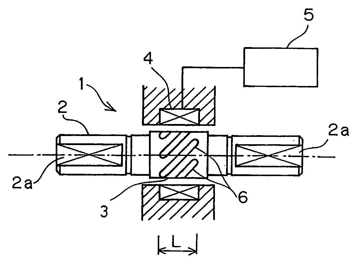
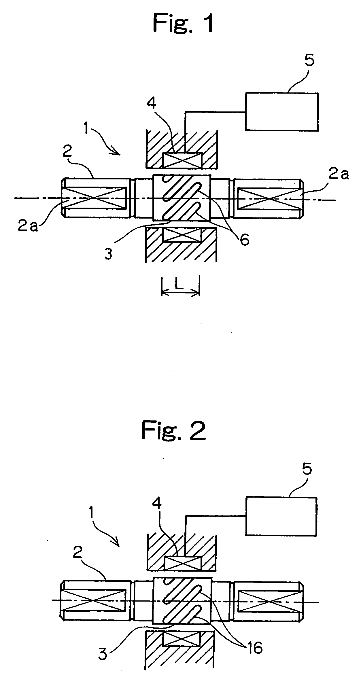
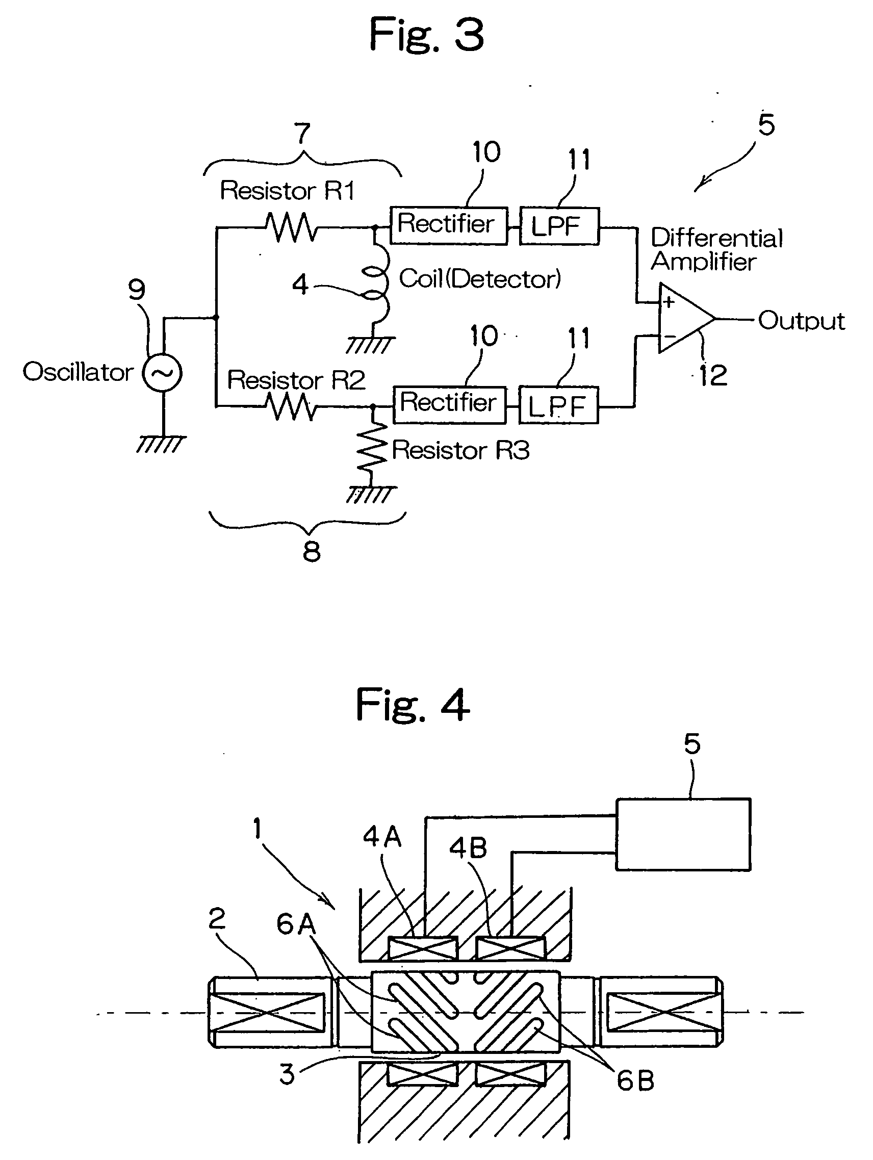
To provide a torque detecting device having a sufficient mechanical strength, capable of accomplishing an accurate torque measurement, having a processability excellent for mass-production, and effective to eliminate problems associated with damages which would be brought about during a heat treatment. This torque detecting device includes a target area subject to torque detection (3) provided in a surface region of a torque transmitting shaft (2) made of a steel material; a detecting coil (4) provided in a non-contact fashion in face-to-face relation to an outer periphery of the target area subject to torque detection (3); and a detection signal processing circuit (5). The target area subject to torque detection (3) is a layer of magnetostrictive material comprised of an Al diffusion layer. This diffusion layer contains Al diffused in a steel material in a concentration which gradually decreases from the surface in a direction radially inwardly of the torque transmitting shaft (2).

Description

FIELD OF THE INVENTION [0001] The present invention relates to a torque detecting device for detecting a loaded torque in a non-contact fashion by detecting a magnetostrictive phenomenon appearing in a surface layer of a shaft when the torque is loaded on such shaft. BACKGROUND ART [0002] In a non-contact magnetostrictive torque detecting device, when a to-be-measured shaft is manufactured using steel for machine structural use, the magnetostrictive phenomenon does not occur so conspicuously that an accurate detection of the torque is difficult to achieve. Accordingly, the torque detecting device has been suggested, in which a special alloy, for example, an Fe-Al alloy is used for the to-be-measured shaft. See, for example, the Japanese Patent No. 2592491. However, since the Fe-Al alloy is hard, but fragile, the mechanical processability is reduced considerably. In a case of a to-be-measured shaft having notches, the torsional fatigue strength and the impact value are also reduced s...

Claims


Application Information

Patent Timeline
Patent Type & Authority Applications(United States)
IPC IPC(8): G01F15/08G01L3/10
CPCG01L3/102G01L5/0009G01L3/103F16C41/00F16C19/06F16C19/186F16C2326/02F16C2380/26
Inventor YOSHIDA, KAZUHIKOKOIKE, TAKASHIIWAMOTO, KENICHI
Owner NTN CORP
Learn More