
Method for local application of diffusion aluminide coating

a technology of diffusion aluminide and local application, which is applied in the direction of solid-state diffusion coating, mechanical equipment, machines/engines, etc., can solve the problems of unstable quality of antioxidation coating, high reliability, and damage to high-temperature metal components subjected to the above-described antioxidation coating, etc., to achieve stable quality, easy application, and stable quality

Inactive Publication Date: 2007-01-11
IHI CORP
View PDF3 Cites 26 Cited by
  • Summary
  • Abstract
  • Description
  • Claims
  • Application Information

AI Technical Summary

Benefits of technology

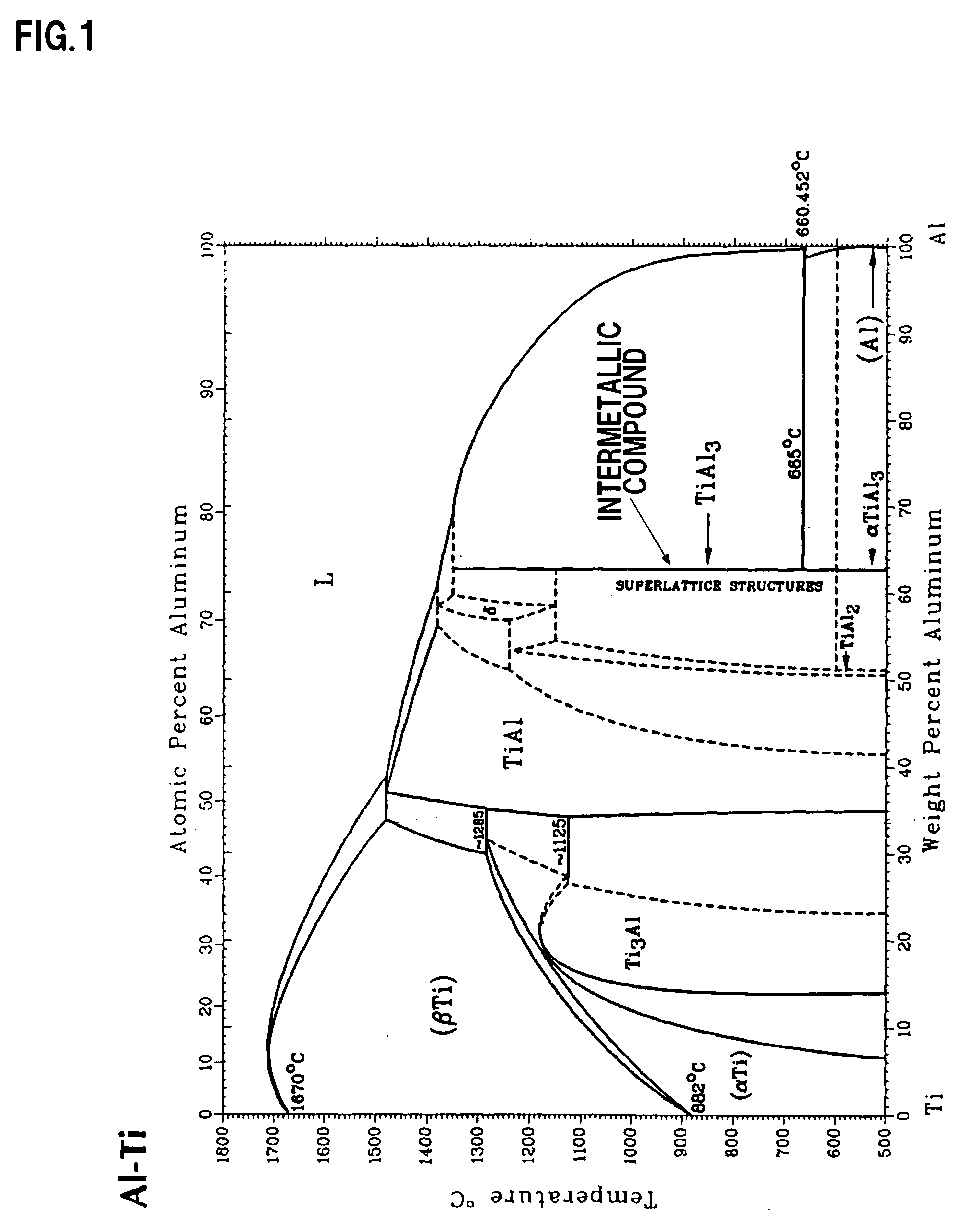
[0031] According to the method of the present invention, coating with stable quality can be readily applied because a coating slurry is prepared using an aluminum-containing intermetallic compound powder (preferably, TiAl3 or αTiAl3), and therefore, an aluminum content is precisely fixed (theoretical ratio: 62.8% by weight).
[0032] It has been confirmed by the embodied examples of the present invention that coating with stable quality can be readily applied to a damaged area of a high temperature metal component without using excess slurry components, which are essentially unnecessary, such as inert ceramic particles and oxide dispersant, and the resulting coating has less cracking or chipping after the oxidation resistance test and therefore has high oxidation resistance.
[0033] The coating thus obtained is an outward diffusion type, and it has also been confirmed that a reduction amount of the base material of a thin blade or vane can be minimized, and repair can be made in repetition.

Problems solved by technology

High-temperature metal components subjected to the above-described antioxidation coating sometimes suffer damages such as chipping in a portion of the coating during operation of a gas turbine or processing of the components.
It has high reliability, but is not cost effective.
In the conventional localized coating method as disclosed in Patent Document 1, however, a blue zone which looks blue because of a high aluminum concentration tends to be formed in the vicinity of the surface and during oxidation resistance test (at 1121° C. for 23 hours in the air) or during use of the component, and coating damages such as cracks and chipping frequently appear in the vicinity of the surface, which make the quality of the coating unstable.
The methods as disclosed in Patent Documents 2 and 3 are inevitably costly, because slurry components not essentially necessary such as inert ceramic particles, aqueous base dispersant, inorganic gel forming agent and oxide dispersant must be added to the slurry.

Method used


Image

  • Method for local application of diffusion aluminide coating
  • Method for local application of diffusion aluminide coating
  • Method for local application of diffusion aluminide coating

Examples


embodied example 1

[0057] For the formation of outward type diffusion coating with higher oxidation resistance, the following coating source and activator were employed.

[0058] Coating source: TiAl3 powder

[0059] Activator: halide (AlF3)

[0060] As the intermetallic compound, TiAl3 having a theoretical aluminum ratio of 62.8% by weight and containing 0.5% or less impurities was used. The coating source and activator were mixed at a weight ratio of 95:5, and a slurry was prepared using a water soluble binder.

[0061] The slurry thus prepared was applied to a damaged area of a metal component. After drying, the metal component was inserted in alumina powder and maintained at 1900 to 2000° F. (1038 to 1094° C.) for 4 hours in an inert gas or hydrogen atmosphere.

[0062] The other steps were performed as described above.

[0063]FIGS. 4A and 4B are cross-sectional photographs of the microstructure showing the example of the present invention. FIG. 4A is a cross-sectional photograph of the coating microstructur...

embodied example 2

[0066]FIGS. 5A, 5B, 5C and 5B are cross-sectional photographs of the microstructure showing other examples of the present invention. In these drawings, FIG. 5A is a cross-sectional photograph of the microstructure of another coating obtained by the above-described invention method, and FIG. 5B is a cross-sectional photograph of the coating microstructure after oxidation resistance test. FIG. 5C is a cross-sectional photograph of the coating microstructure obtained by the above-described conventional method, and FIG. 5D is a cross-sectional photograph of the coating after oxidation resistance test. The oxidation resistance test was carried out under conventional test conditions (at 1121° C. for 23 hours in the air).

[0067] When only oxidation resistance is taken into account, an aluminum concentration is preferably higher. When an aluminum concentration is excessively high, however, the coating becomes very brittle, chipping or cracks tend to appear, and the coating shows less oxidat...


PUM

PropertyMeasurementUnit
Temperatureaaaaaaaaaa
Fractionaaaaaaaaaa
Timeaaaaaaaaaa

Abstract

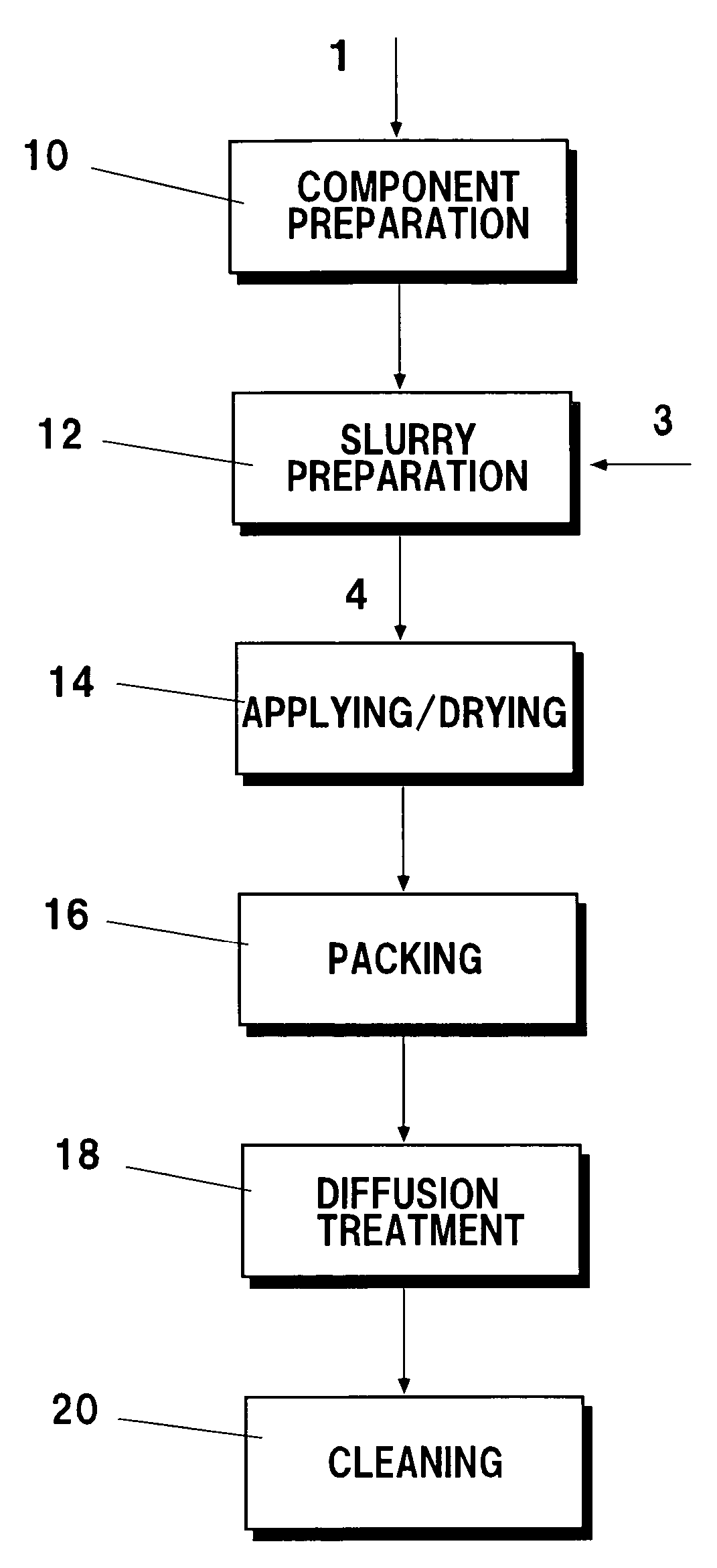
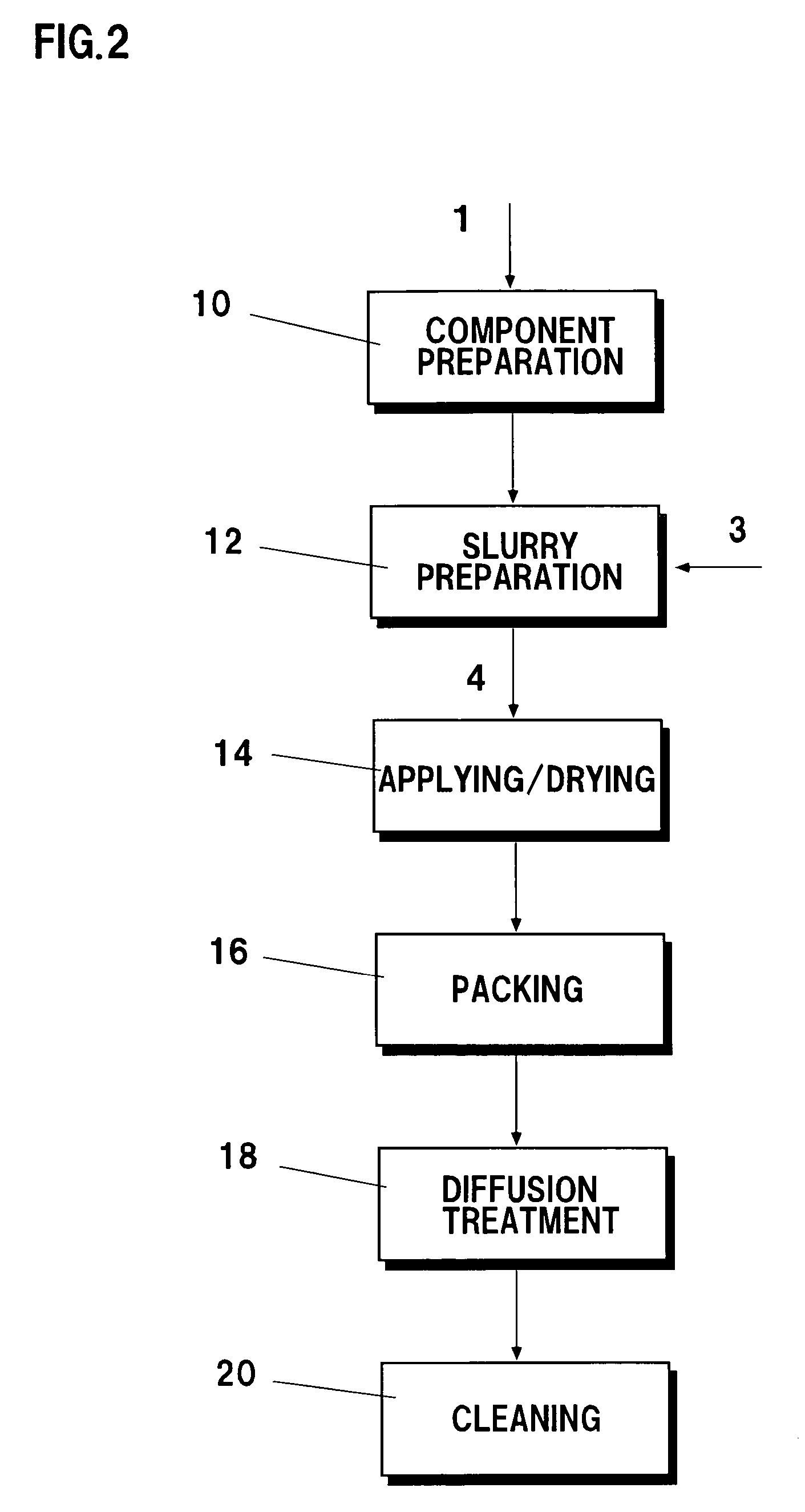
A method includes a component preparation step 10 of exposing local areas (damaged areas of an existing coating) of a base material of a metal component 1 to be coated, and roughening a surface of the base material to a desired surface roughness, a slurry preparation step 12 of preparing a coating slurry that contains a halide activator, a water soluble organic binder, and powder of an aluminum-containing intermetallic compound 3, an application and drying step 14 of applying the coating slurry to the damaged areas of the metal component, and then drying the areas, a packing step 16 of packing the metal component in a heat-resistant container filled with alumina powder, a diffusion treatment step 18 of retaining the heat-resistant container at high temperature in an inert atmosphere or a reducing atmosphere to diffuse aluminum onto the surface of the metal component, and a cleaning step 20 of taking out the metal component from the heat resistant container, and removing a slag from the surface of the metal component.

Description

BACKGROUND OF THE INVENTION [0001] 1. Technical Field of the Invention [0002] The present invention relates to a method for local application of diffusion aluminide coating, capable of reducing generation of cracks and attaining high oxidation resistance. [0003] 2. Description of Related Art [0004] In gas turbines for jet engine or gas turbines for land power generation, it is the common practice to apply antioxidation coating onto the surface of metal components exposed to a high temperature gas (which components will hereinafter be called “high temperature metal components”) such as blade, vane, shroud and combustor in order to improve their oxidation resistance. [0005] Such antioxidation coating is formed by keeping a component to be coated at a predetermined temperature in a condition abundant in a specified element (mainly, aluminum). [0006] High-temperature metal components subjected to the above-described antioxidation coating sometimes suffer damages such as chipping in a po...

Claims


Application Information

Patent Timeline
IPC IPC(8): B05D3/00C23C16/00
CPCC23C10/02C23C10/04C23C10/18C23C10/30F05D2230/80F01D5/005F01D5/288F05D2230/90F05D2300/611C23C10/48
Inventor SASAKI, AKIKOOHI, NARIHITOMUNEDA, SHIGEKAZUTAKAHASHI, HIDEO
Owner IHI CORP
Learn More