Equipment for measuring distribution of void or particle size

Inactive Publication Date: 2007-01-11
RIGAKU CORP
View PDF7 Cites 10 Cited by
  • Summary
  • Abstract
  • Description
  • Claims
  • Application Information

AI Technical Summary

Benefits of technology

[0015] An object of the invention is to provide a pore- or particle-size distribution measurement apparatus capable of measuring pore or particle size in a short period of time with high accuracy.
[0029] According to the invention, since the position-sensitive X-ray detector is used, it is possible to detect an X-ray intensity as a distribution including position data and detect generation of scattered X-ray components with high efficiency, thereby allowing highly accurate measurement in a short time period.
[0034] According to the invention, since no slit is used at the X-ray detecting means side, while in the X-ray generating means, a point focus X-ray tube is employed at the X-ray generating means side, this makes it possible to improve the detection efficiency in a region where the scattering angle is large. Moreover, the use of a two-dimensional type position-sensitive X-ray detector makes it possible to analyze scattering information in a two-dimensional manner. Thus, even if a microstructure such as a pore or particle structure existing within the insulator film exhibits being anisotropic, it can be analyzed properly.
[0036] According to the invention, it is possible to prevent a specular reflection component having high intensity from entering the position-sensitive X-ray detector. It is thereby possible to block off an excessive specular reflection component having high intensity and detect with high accuracy the target scattered component to be detected.
[0041] According to the invention, the X-rays undergo convergence and enter a specimen prepared as the measurement target object. This makes it possible to enhance X-ray utilization efficiency and thereby perform satisfactory measurement. Moreover, the same as in the above-described constructions, it is possible to ensure compatibility between the detection efficiency and the resolving power with respect to the scattering angle.
[0043] According to the invention, the X-ray irradiation range regulatory plate is arranged immediately above a measurement point on the specimen prepared as the measurement target object at a predetermined spacing, for regulating an irradiation range on the specimen. This helps prevent X-rays from spreading out widely on the specimen, whereby making it possible to find out the positional dependence of the pore or particle size distribution on the specimen with high accuracy.

Problems solved by technology

This is however time consuming, because X-ray intensity measurement needs to be performed on an incident angle-by-incident angle θi basis.
Resultantly no X-rays are allowed to enter the insulator film 3, making it impossible to achieve measurement.
Resultantly, after the reflection, the components scattered by a pore Y are superimposed intensely, making it difficult to achieve measurement.
As seen from the foregoing, if measurement cannot be achieved easily in a region where the scattering angle is small, it will be difficult to determine distribution in a region where the pore size is larger.
Another problem is that, of the X-rays scattered widely, only the narrowly-limited angle components cut out by the solar slit 35 and the light-receiving slit 36 are detected, which may lead to very poor X-ray exploitation efficiency.
Its influence gives rise to problems of the S / N (signal to noise) ratio being deteriorated particularly in a region where the scattering angle is large, and determination of distribution being difficult in a region where the pore size is smaller.
Such a problem may also arise in the presence of particles.

Method used


Image

  • Equipment for measuring distribution of void or particle size
  • Equipment for measuring distribution of void or particle size
  • Equipment for measuring distribution of void or particle size

Examples


embodiment 1

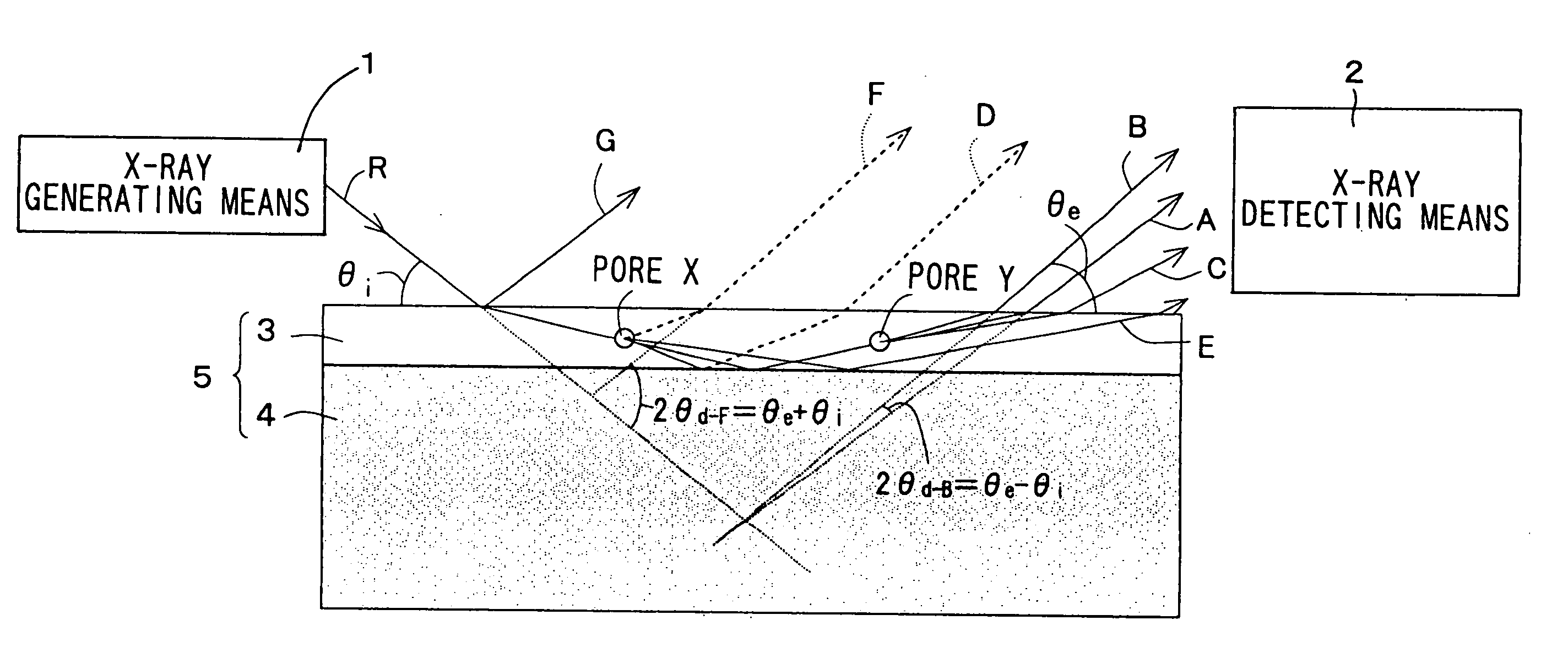
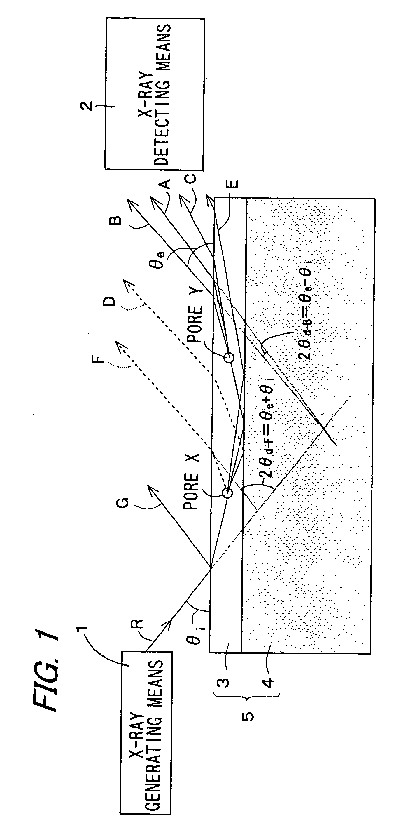
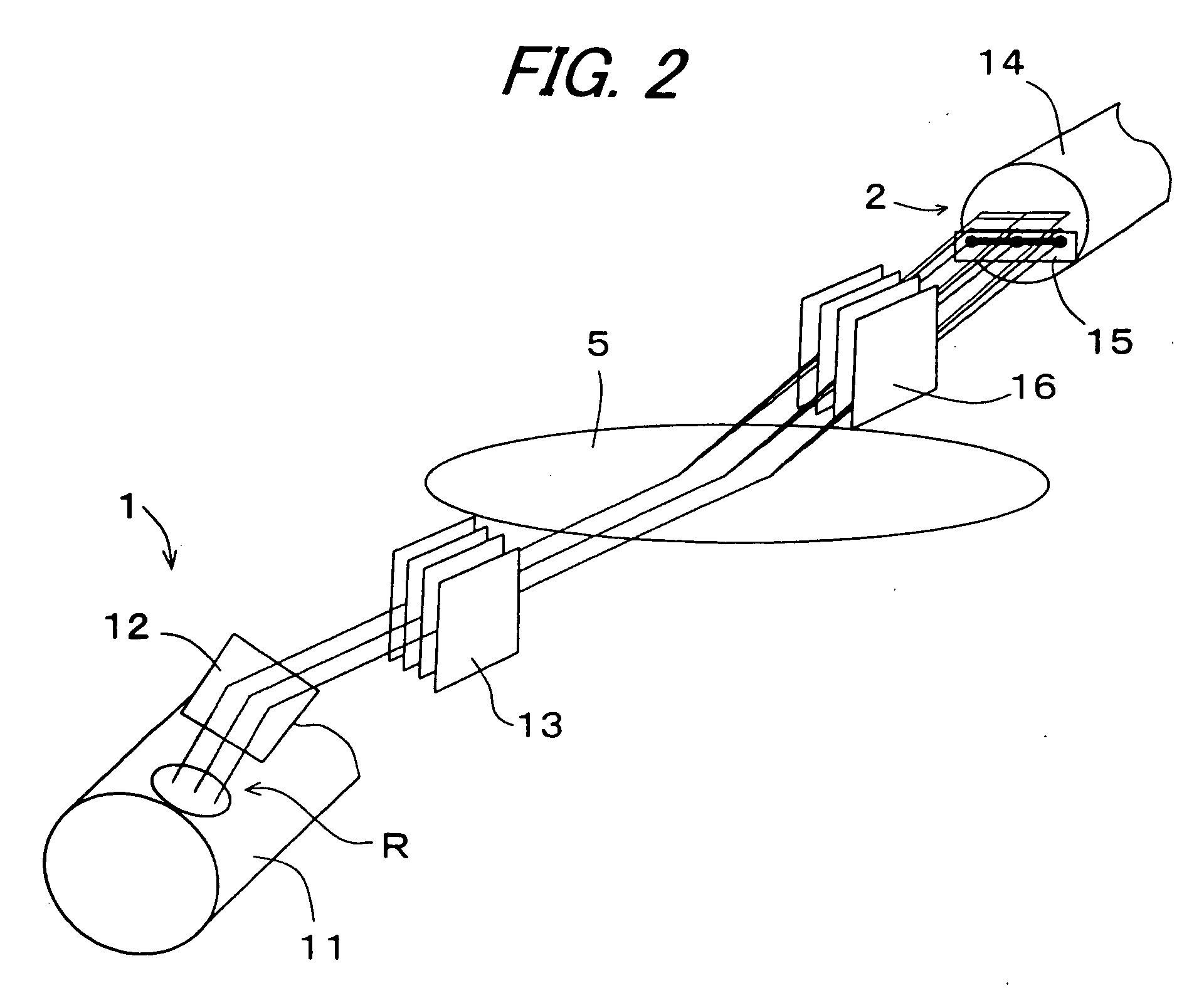
[0089]FIG. 2 shows the concrete structure of the first embodiment of the pore-size distribution measurement apparatus. The X-ray generating means 1 is provided with a linear focus X-ray tube 11; a spectroscope 12; and a solar slit 13. The X-ray detecting means 2 is provided with a position-sensitive X-ray detector 14; a reflection X-ray blocking plate 15; and a solar slit 16. Note that the X-ray generating means 1 of this construction is designed to allow a substantially linear parallel light flux, composed of specific-direction components which are mutually parallel and exist in a specific wavelength or wavelength band, to enter the specimen 5 at an incident angle of θi.

[0090] In the linear focus X-ray tube 11, an electron emanating from a linear cathode is applied to an anode, and the resultant component is discharged obliquely from a window arranged in a direction such that it may appear to be narrower and longer. The X-ray R emitted from the X-ray tube 11 changes its optical pa...

embodiment 2

[0105] As compared with the apparatus of conventional design, the pore-size distribution measurement apparatus having a structure such as shown hereinabove allows measurement more accurately at higher speed. Now, consideration will be given to the detection efficiency in a region where the scattered component is low in X-ray intensity and large in scattering angle. As shown in FIG. 8, since a scattered component BL having a large scattering angle is spread out more widely compared to a scattered component BS having a small scattering angle, it follows that that portion BLt of the scattered component BL which passes through the solar slit 16 is smaller in quantity than that portion BSt of the scattered component BS which passes through the solar slit 16. That is, it has been found that scattered components having larger scattering angles are intensively blocked off by the solar slit 16 so as not to reach the X-ray detector 14.

[0106] Thence, in the second embodiment of the invention,...

embodiment 3

[0119] Although the first and second embodiments thus far described deal with the case where a light flux composed of mutually-parallel X-rays is applied to a specimen, the following technique has also been known. Shown in FIG. 14 is an X-ray converging optical system in which X-rays emitted spreadingly from the point focus X-ray tube 17 converge to a point by means of an X-ray condensing element 22 and an aperture 23. At the focusing point is placed the position-sensitive X-ray detector 14. Between the X-ray converging optical system and the position-sensitive X-ray detector 14 is placed a specimen M. With this structure, it is possible to ensure compatibility between the detection efficiency and the resolving power with respect to the scattering angle. FIG. 14 is a constitution diagram showing a constitution example of the X-ray converging optical system described just above.

[0120] Thence, in the third embodiment, the pore-size distribution measurement apparatus is constructed by...


PUM


Abstract

A pore- or particle-size distribution measurement apparatus capable of measuring the size of a pore or a particle in a short time with high accuracy, is provided. When the size of a pore (Y) existing in a porous insulator film (3) or the size of a particle in a thin film is measured, a specimen (5) having the insulator film (3) formed on the surface of a substrate (4) is irradiated, from the surface side thereof, with X-rays R at a specified incident angle θi larger than the total reflection critical angle of the insulator film (3) but not exceeding 1.3 times the total reflection critical angle of the substrate (4). In the irradiated X-rays, among components exiting from the insulator film (3) without entering the pore (Y) and scattering of reflection component of the X-rays reflected on the surface of the substrate (4) after having entered the insulator film (3), the scattered component whose exit angle is larger than that of a component of the reflection component which exits from the insulator film (3) without entering the pore (Y) is detected.

Description

TECHNICAL FIELD [0001] The present invention relates to a pore- or particle-size distribution measurement apparatus that is suitably used in measuring sizes of pores existing in an ultra-low dielectric constant insulator or the like in the process of forming the ultra-low dielectric constant insulator for use in a wiring formation step which is one of steps for manufacturing a semiconductor integrated circuit. BACKGROUND ART [0002] Year by year, improvements have been sought after in a semiconductor integrated circuit with respect of high-speed performance, power saving and high integration. Thus, in recent years, it has come to be demanded that wiring resistance is reduced by employing a copper wiring, and as well the dielectric constant of an insulator (insulator film) interposed between wiring lines is reduced (reduction in Low-k value), thereby reducing parasitic capacitance between the wiring lines. The insulator is formed as a thin film on a surface of a semiconductor substrat...

Claims


Application Information

Patent Timeline
IPC IPC(8): G01N23/20G01N15/02G01N15/08G01N15/14G01N23/203
CPCG01N15/0205G01N2015/086G01N2015/0846G01N23/203
Inventor TERADA, SHINICHI
Owner RIGAKU CORP
Why Eureka
Try Eureka