Particle detecting module

Active Publication Date: 2019-10-31
MICROJET TECH
View PDF0 Cites 1 Cited by
  • Summary
  • Abstract
  • Description
  • Claims
  • Application Information

AI Technical Summary

Benefits of technology

The present disclosure provides a particle detecting module for a thin-type portable device. The module has an inlet to get air into it, a heating system to maintain standard humidity, and a detecting chamber with a one-way opening to allow air to flow in and out. This allows for efficient detection of particles, and the main body of the module is thin enough to be applied to a portable device for instant measuring.

Problems solved by technology

Fine suspended particles are so small that they can easily enter the lungs of the human body since it is difficult to obstruct them by the nasal hair in the nasal cavity.
If other pollutants are attached to the suspended particles, the injury to the respiratory system of the human body can be even worse.
In other words, the concentration of suspended particles cannot be provided at anytime and anywhere.
In addition, the interference caused by water vapor with the detection of suspended particles is not prevented.
Under this circumstance, the light transmittance thereof becomes insufficient, and the small water molecules (water droplets) in the air are increased, which will directly affect the accuracy of the detection.

Method used


Image

  • Particle detecting module
  • Particle detecting module
  • Particle detecting module

Examples


first embodiment

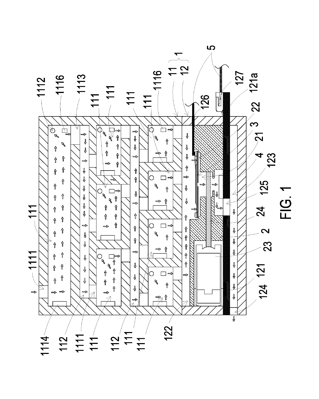
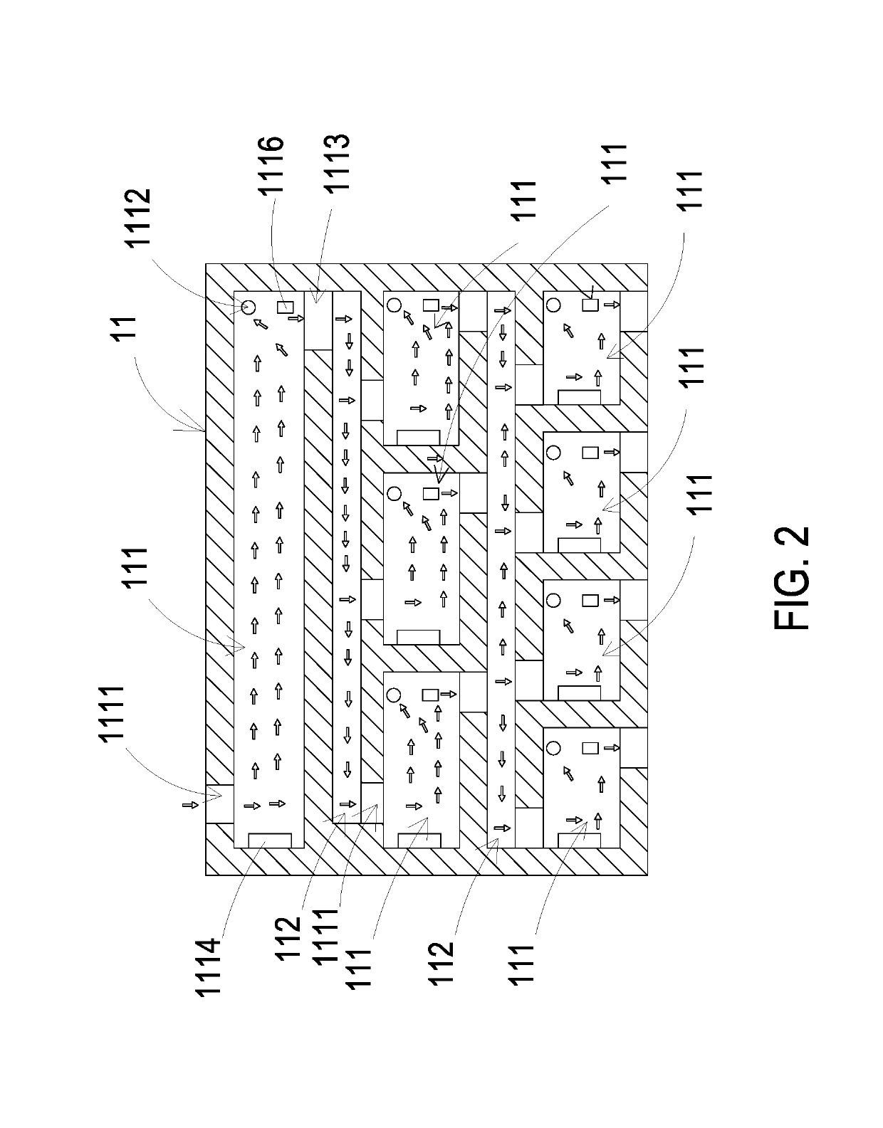
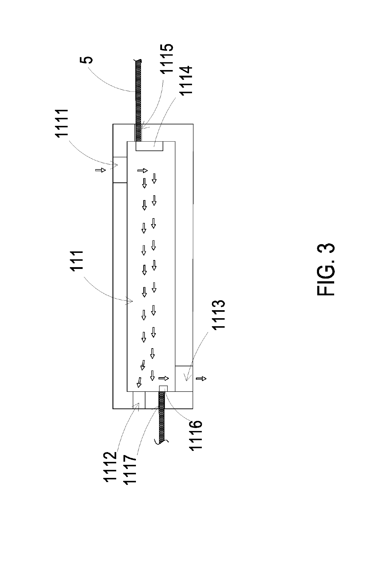
[0028]The present disclosure provides a particle detecting module. Please refer to FIGS. 1 to 3. According to the present disclosure, the particle detecting module includes a main body 1, a fine particle detecting base 2, an actuator 3 and a sensor 4. The main body 1 includes an air guiding part 11 and a detecting part 12 which are combined with each other. The air guiding part 11 includes a plurality of storage chambers 111 and a plurality of airflow channels 112. Each storage chamber 111 includes an inlet aperture 1111, a heat-dissipation aperture 1112, an outlet aperture 1113 and a heating element 1114. After the air is inhaled into the storage chamber 111 through the inlet aperture 1111, the heating element 1114 heats the air in the storage chamber 111 to achieve a heating and dehumidification operation, and the water vapor generated thereby is discharged out from the storage chamber 111 through the heat-dissipation aperture 1112. Finally, the heated and dehumidified air is disc...

second embodiment

[0049]Please refer to FIGS. 12A, 12B and 13A. In the second embodiment, the actuator 3′ is a gas pump and includes an air inlet plate 31′, a resonance plate 32′, a piezoelectric actuator 33′, a first insulation plate 34′, a conducting plate 35′ and a second insulation plate 36′. The air inlet plate 31′, the resonance plate 32′, the piezoelectric actuator 33′, the first insulation plate 34′, the conducting plate 35′ and the second insulation plate 36′ are stacked and assembled sequentially.

[0050]In the second embodiment, the air inlet plate 31′ has at least one inlet 31a′, at least one convergence channel 31b′ and a convergence chamber 31c′. The convergence channel 31b′ is disposed and spatially corresponding to the inlet 31a′. The inlet 31a′ allows the air to be inhaled therethrough. The air inhaled through the inlet 31a′ is guided to the convergence chamber 31c′ through the convergence channel 31b′. The resonance plate 32′ has a central aperture 32a′, a movable part 32b′ and a fixe...

third embodiment

[0053]Please refer to FIG. 13B. the suspension plate 33a′ is formed by stamping to make it extend at a distance in a direction away from the resonance plates 32′. The extended distance can be adjusted through the at least one bracket 33c′ formed between the suspension plate 33a′ and the outer frame 33b′. Consequently, the top surface of the bulge 33f′ disposed on the suspension plate 33a′ and the coupling surface the outer frame 33b′ are non-coplanar. By utilizing a small amount of filling materials, such as a conductive adhesive applied to the coupling surface of the outer frame 313b, the piezoelectric actuator 33′ is attached to the fixed part 32c′ of the resonance plate 32′ by heat pressing, thereby assembling the piezoelectric actuator 33′ and the resonance plates 32′ in combination. Thus, the structure of the chamber space 37′ is improved by directly stamping the suspension plate 33a′ of the piezoelectric actuator 33′ described above. In this way, the required chamber space 37...


PUM


Abstract

A particle detecting module is disclosed and includes a main body, which is consist of an air guiding part and a detecting part, by driving a plurality of heating elements disposed within a plurality of storage chambers of the air guiding part, air inside these storage chambers is heated and the moisture of the air is removed, and then the air is transported to the detecting part, so that a sensor of the detecting part could detect the sizes and the concentrations of the suspended particles, and the interference of the humidity is reduced.

Description

FIELD OF THE DISCLOSURE[0001]The present disclosure relates to a particle detecting module, and more particularly to a particle detecting module capable of maintaining a standard humidity level of the air and capable of being assembled to a thin-type portable device for air monitoring.BACKGROUND OF THE DISCLOSURE[0002]Suspended particles refer to solid particles or droplets contained in the air. Fine suspended particles are so small that they can easily enter the lungs of the human body since it is difficult to obstruct them by the nasal hair in the nasal cavity. The fine suspended particles entered in the human body can cause inflammation, asthma or cardiovascular disease in the lungs. If other pollutants are attached to the suspended particles, the injury to the respiratory system of the human body can be even worse.[0003]Mostly, the conventional gas detecting modules are set in fixed-point type, and only the air information around the air observation station can be measured. In o...

Claims


Application Information

Patent Timeline
IPC IPC(8): G01N1/44B01D53/00G01N33/00G01N15/02G01N15/06G01N15/14
CPCB01D53/005G01N15/1404G01N33/0022G01N15/0606G01N15/0656G01N33/0014G01N15/0211G01N33/0073G01N1/44G01N15/0205G01N15/06G01N15/1459G01N2001/2261G01N2015/0046G01N2035/00455
Inventor MOU, HAO-JANHUANG, CHI-FENGHAN, YUNG-LUNGCHEN, HSUAN-KAI
Owner MICROJET TECH
Why Eureka
Try Eureka