Light-emitting apparatus and method for forming the same

Inactive Publication Date: 2006-07-04
TOYOTA IND CORP
View PDF17 Cites 17 Cited by
  • Summary
  • Abstract
  • Description
  • Claims
  • Application Information

AI Technical Summary

Benefits of technology

[0018]Further, a third objective of the present invention is to provide a light-emitting apparatus that, when used as a reflection plate, not only prevents specular reflection, but also has a high brightness in a specific direction when receiving light in a direction of an hypothetical light source. The present invention also pertains to a method for forming such an apparatus.

Problems solved by technology

Such light-emitting apparatuses are known for low extraction efficiency.
In these cases, however, when the light-emitting layer is not producing light, specular reflection of external light occurs.
However, as in the first prior art, forming an uneven surface having asperities on the substrate and forming light-emitting device on the uneven surface does not necessarily improve the extraction efficiency.
Also, depending on the shapes of the asperities, the following problems occur.
Further, the phenomenon causes a significant amount of current to pass through specific portions of the light-emitting layer 211, and thus shortens the lifetime of these portions.

Method used


Image

  • Light-emitting apparatus and method for forming the same
  • Light-emitting apparatus and method for forming the same
  • Light-emitting apparatus and method for forming the same

Examples


Embodiment Construction

[0053]Several embodiments of the present invention will now be described with reference to the drawings. Same reference numerals are similar or the same in the drawings. A first organic EL apparatus will now be described.

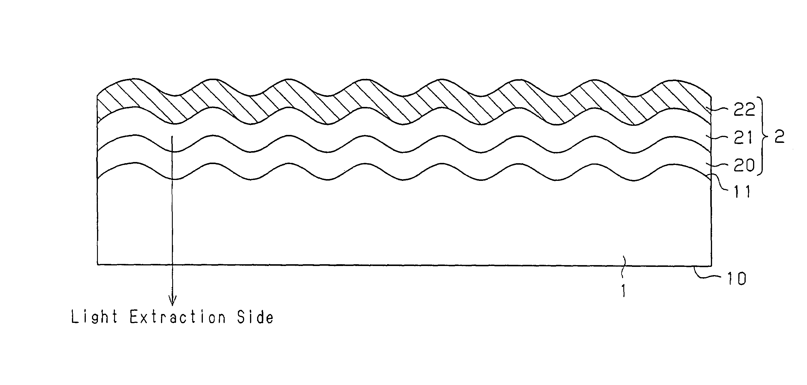
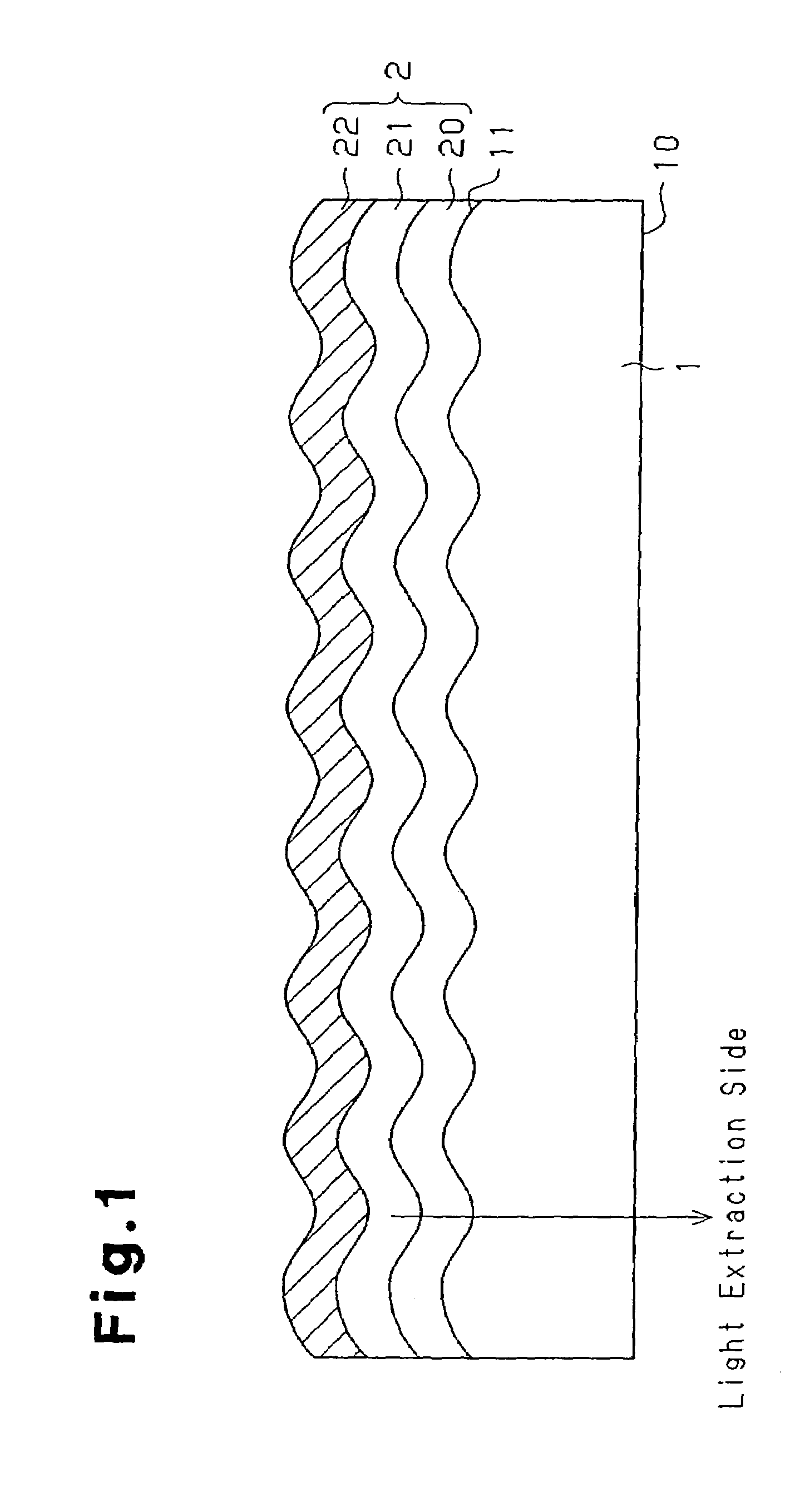
[0054]As shown in FIG. 1, the first organic EL apparatus is of a bottom emission type that includes a transparent substrate 1 and an organic EL device 2. Asperities are formed on one face of the transparent substrate 1 (a incident surface 11). In other words, the incident surface 11 is an uneven surface. The organic EL device 2 is formed on the incident surface 11.

1>

[0055]The substrate 1 is a substantially plate-shaped transparent member that supports the organic EL device 2. The substrate 1 has the incident surface 11 on which the organic EL device 2 is formed, and a light exit surface 10 that is located opposite from the incident surface 11. The substrate 1 receives light from the organic EL device 2 through the incident surface 11, and emits the received light th...


PUM


Abstract

In a light-emitting apparatus, a face of a substrate on which a light-emitting device is formed is an uneven surface having a plurality of asperities. The mean spacing Sm of adjacent asperities or the mean spacing S of peaks of adjacent projections of the asperities is no less than three times the longest wavelength of light generated by a light-emitting layer and no more than two hundred times the longest wavelength. The arithmetic mean slope Δa of the uneven surface is in a range between 4° and 30°, inclusive. Therefore, the apparatus emits substantially a greater amount of light from a light extraction side and has less brightness unevenness than a light-emitting apparatus with no uneven surface.

Description

BACKGROUND OF THE INVENTION[0001]The present invention relates to a light-emitting apparatus having a substrate on which a light-emitting device is formed. The light-emitting device is an organic electroluminescent device (organic EL device) or an inorganic electroluminescent element (inorganic EL elements). Such a device has a light-emitting layer held between a pair of electrodes. The present invention also pertains to a method for forming the apparatus.[0002]Lighting systems and displays using a light-emitting apparatus such as an organic electroluminescent apparatus (organic EL apparatus) and an inorganic electroluminescent apparatus (inorganic EL apparatus) have been proposed.[0003]Such light-emitting apparatuses are known for low extraction efficiency. That is, the ratio of the light that is extracted outside from the apparatus to the light generated by a light-emitting layer is low. This is because layers forming a light-emitting apparatus have different refractive indices.[0...

Claims


Application Information

Patent Timeline
IPC IPC(8): H01J1/62B32B3/10H01J63/04H05B33/22H01L51/52
CPCH01L51/52H01L51/5262Y10T428/24347H10K59/875H05B33/22H10K50/80H10K50/85
Inventor UTSUMI, DECEASED, TETSUYAUTSUMI, LEGAL REPRESENTATIVE, TOMOKOARIMA, MASAAKIHARADA, MASAYUKIFUNADA, MARI
Owner TOYOTA IND CORP
Why Eureka
Try Eureka