Backlight module and light guide plate thereof

Inactive Publication Date: 2006-03-28
HON HAI PRECISION IND CO LTD
View PDF6 Cites 14 Cited by
  • Summary
  • Abstract
  • Description
  • Claims
  • Application Information

AI Technical Summary

Benefits of technology

[0012]An object of the present invention is to provide a backlight module having a high brightness, which is in low cost, and which is efficiently uses light energy.

Problems solved by technology

However, in the conventional backlight module 1 as described above, since a plurality of discrete elements are used, the light emitted from the light source to the liquid crystal panel passes through a number of light interfaces, so light energy is lost.
Further, the backlight module is expensive due to the high cost of the brightness enhancing film used therein.
However, in practice, controlling a precise vertex angle of the V-shaped grooves 232 to be 60–120 degrees as extracted from the mold, is difficult, and it is difficult to get the surfaces of the grooves to be smooth.

Method used


Image

  • Backlight module and light guide plate thereof
  • Backlight module and light guide plate thereof
  • Backlight module and light guide plate thereof

Examples


first embodiment

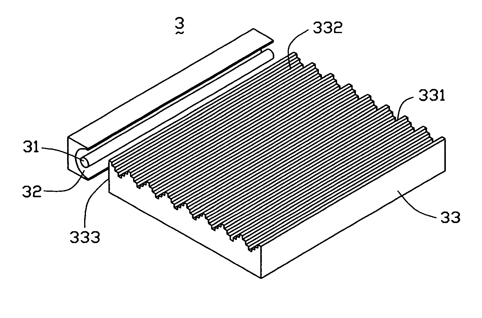
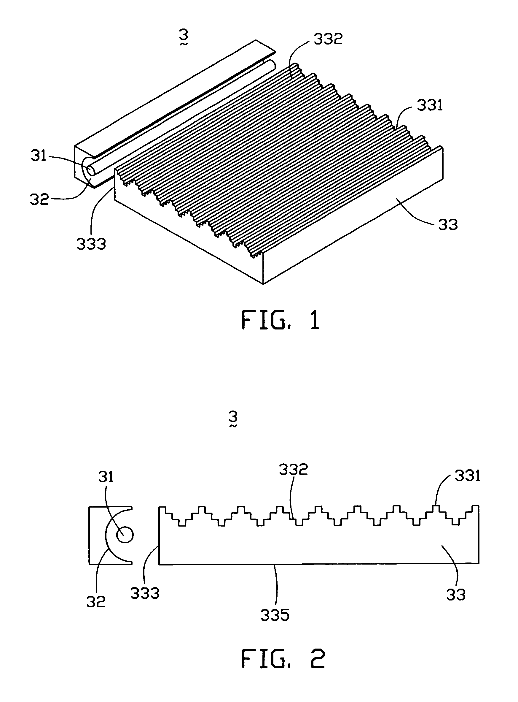
[0027]FIGS. 1 and 2 are respectively a perspective view and a side view of a backlight module according to a The backlight module 3 comprises a light source 31, a light cover 32, and a light guide plate 33, wherein, the light guide plate 33 includes an incident surface 333, an emitting surface 331, and a bottom surface 335 opposite to the emitting surface 331 and orthogonal to the incident surface 333.

[0028]Further, a plurality of stairway-shaped protrusions 332 are uniformly located on the emitting surface 331. Each stairway-shaped protrusion 332 consists of several rectangular steps for collimating the light beams emitted away from the central area of the emitting surface 331. The stairway-shaped protrusions 332 efficiently improve the modulation transfer function (referred as to the MTF) of the light guide plate 33, and increase the brightness of the backlight module 3. The widths of the rectangular steps of the protrusions 332 should be uniform, or should gradually increase as ...

second embodiment

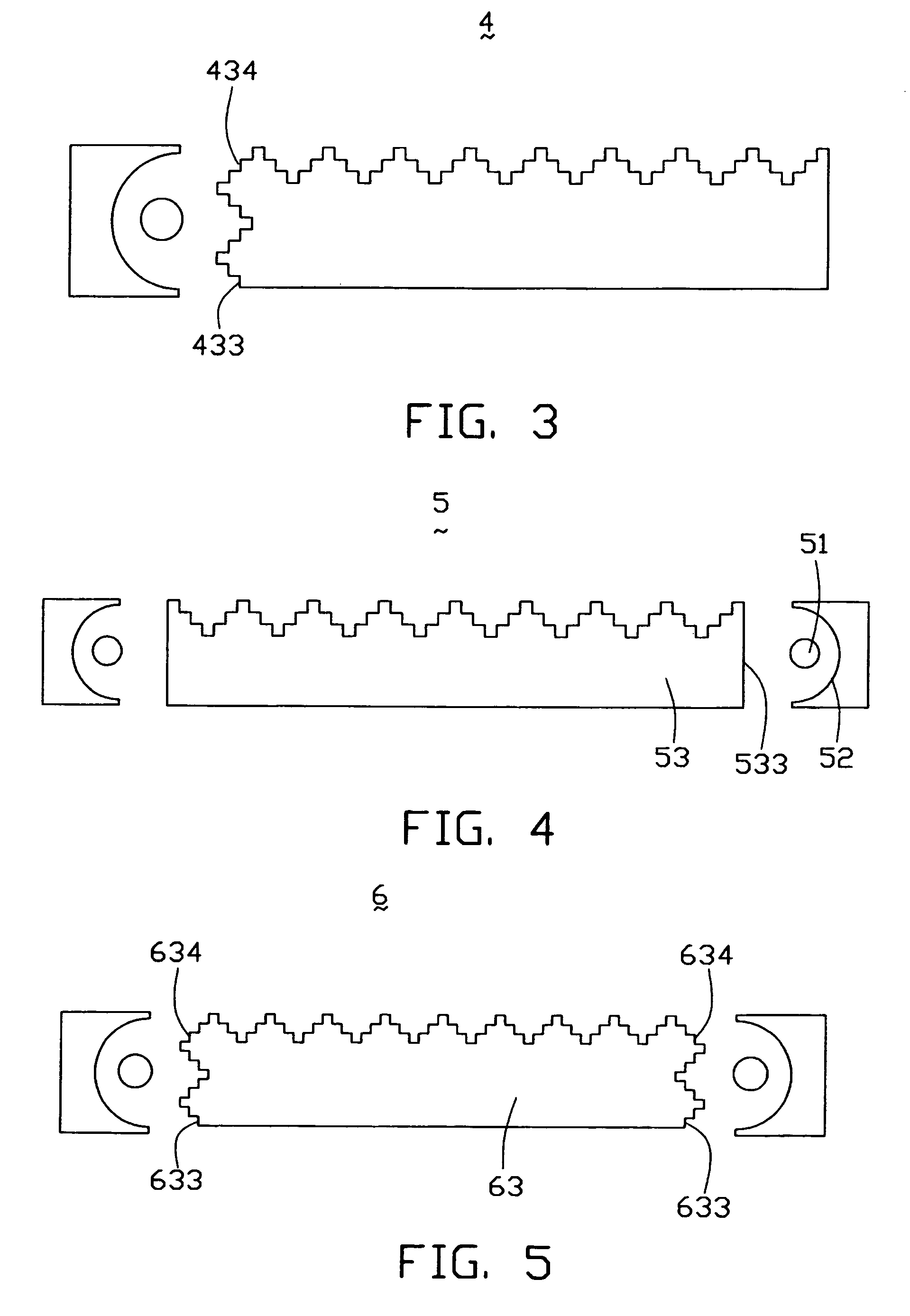
[0030]FIG. 3 illustrates a side view of a backlight module 4 according to a Compared with the backlight module 3 of FIG. 2, the backlight module 4 further comprises a plurality of stairway-shaped protrusions 434 uniformly located on an incident surface 433. The stairway-shaped protrusions 434 mate with the stairway-shaped protrusions on the emitting surface and can far improve the MTF of the light guide plate.

third embodiment

[0031]FIG. 4 illustrates a side view of a backlight module 5 according to a Compared with the backlight module 3 of FIG. 2, the backlight module 5 comprises two light sources 51 and two light covers 52, and a light guide plate 53. The light guide plate 53 includes an incident surface 533 on each of two opposite ends thereof. The light sources 51 are positioned facing to the corresponding incident surfaces 533.


PUM


Abstract

A backlight module (3) includes a light source (31), a light cover (32), and a light guide plate (33). The light guide plate includes an incident surface (333), an emitting surface (331), and a bottom surface (335) opposite to the emitting surface for scattering and reflecting the light beams input by the light source. The light beams are directed by the bottom surface to the emitting surface. A plurality of stairway-shaped protrusions (332) are uniformly located on the emitting surface. The stairway-shaped protrusions can efficiently improve the modulation transfer function of the light guide plate, and increase the brightness of the backlight module.

Description

BACKGROUND OF THE INVENTION[0001]1. Field of the Invention[0002]The present invention relates to a backlight module and light guide plate thereof, and particularly to a high brightness backlight module and light guide plate thereof.[0003]2. Description of Related Art[0004]Conventional backlight modules for use in rear projection displays such as liquid crystal displays are classified into two types, the edge-type and the direct type, depending upon the position of the light sources in the displays. Edge-type backlight modules are usually used in liquid crystal displays because they save space due to their thinness.[0005]One conventional edge-type backlight module has a structure as shown in FIG. 9. In this figure, the conventional backlight module 1 includes a light source 11, a light cover 12, a light guide plate 13, a reflective sheet 14, and a brightness enhancing film 15.[0006]The light guide plate 13 comprises an incident surface 131 for receiving incident light emitted from th...

Claims


Application Information

Patent Timeline
IPC IPC(8): F21V8/00G02B6/00
CPCG02B6/0016G02B6/0038G02B6/0046
Inventor CHEN, GA-LANE
Owner HON HAI PRECISION IND CO LTD
Why Eureka
Try Eureka