Optical rangefinder for an electro-active lens

Inactive Publication Date: 2007-12-06
MITSUI CHEM INC
View PDF11 Cites 51 Cited by
  • Summary
  • Abstract
  • Description
  • Claims
  • Application Information

AI Technical Summary

Benefits of technology

[0022]In an embodiment of the invention a range finding device may be operably coupled to an electro-active lens. The range finding device may include a transmitter for transmitting electro-magnetic energy to an object. The range finding device may further include a receiver for receiving a reflection of at least a portion of the electro-magnetic energy from the object. The range finding device may further include an optical isolator for primarily allowing a diffuse reflection to reach the receiver and for substantially preventing a specular reflection from reaching the receiver. The range finding device may further include a controller operably coupled to the receiver for determining an optical power of the electro-active lens based on an intensity of the diffuse reflection.
[0

Problems solved by technology

This loss of accommodation results in an inability to focus on near objects.
There are problems associated with these two approaches that can be objectionable to some patients.
Additionally, the abrupt change in optical power between regions may cause image jump.
The smooth transition regions associated with progressive addition lenses cause unwanted astigmatism in the lens leading to blurred and distorted vision, which, in some patients, causes physical discomfort.
Furthermore, in both approaches, the placement of the near vision correction area near the bottom edge of the lens requires patients to adopt a somewhat unnatural downward gaze for near vision tasks.
Non-conventional errors of the eye include higher-order aberrations, irregular astigmatism, and ocular layer irregularities.

Method used


Image

  • Optical rangefinder for an electro-active lens
  • Optical rangefinder for an electro-active lens
  • Optical rangefinder for an electro-active lens

Examples


first embodiment

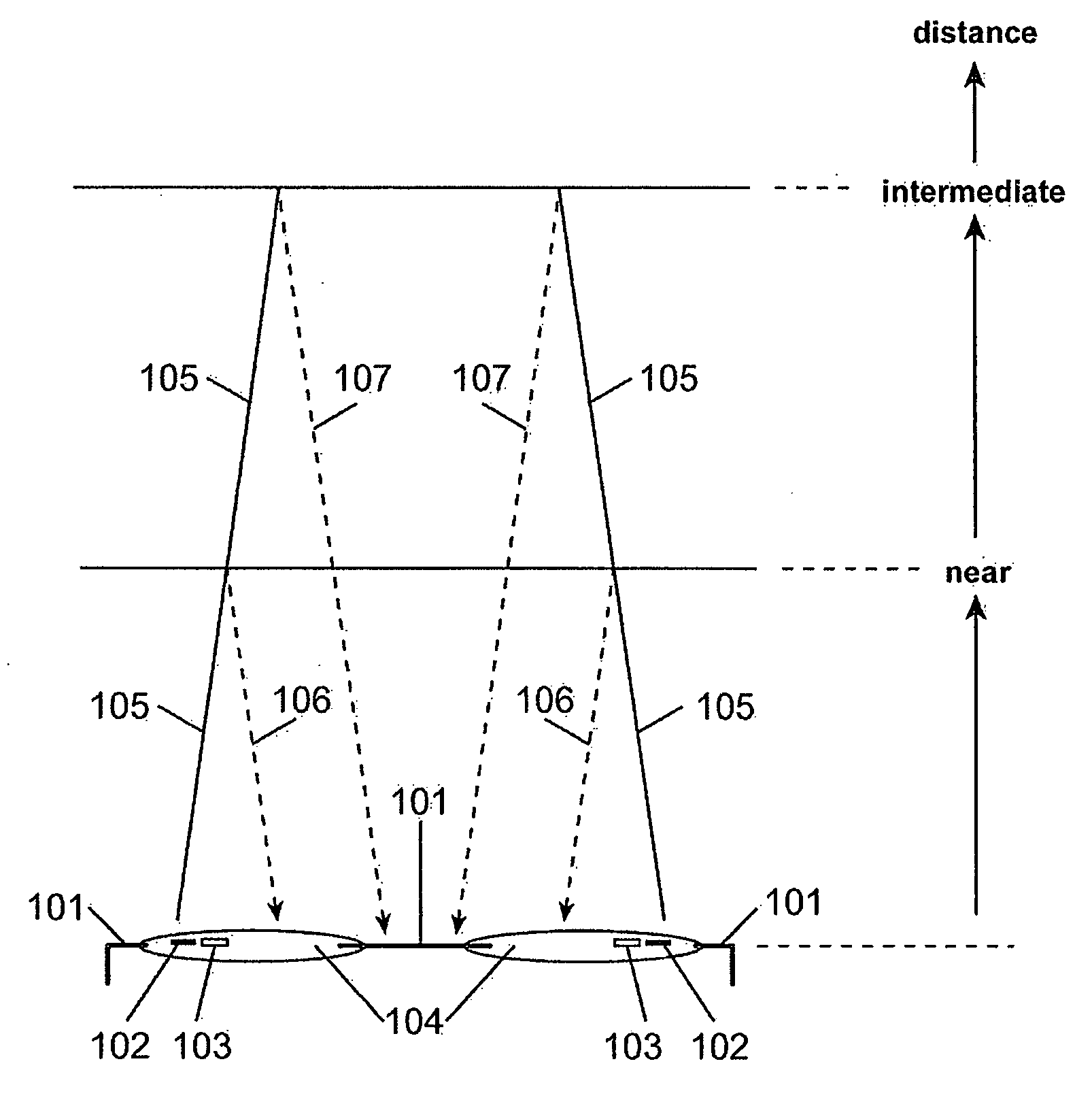
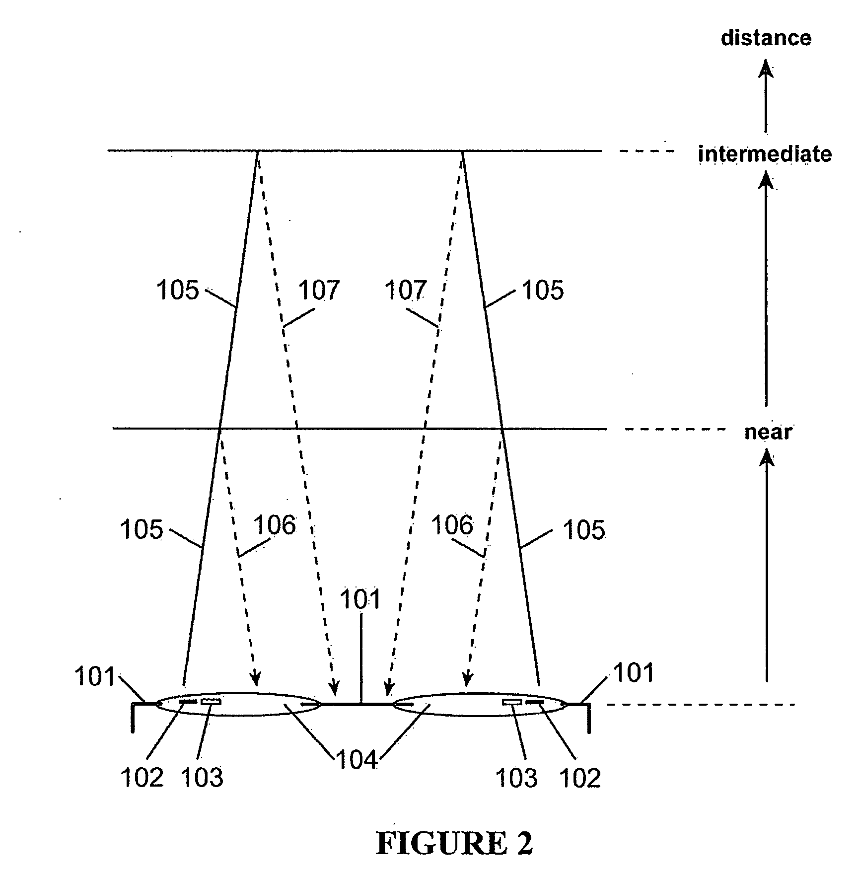
[0044]In the invention shown in FIG. 2, a pair of electro-active spectacles 101 has a controller (not shown) connected to a range finding transmitter 102 and a range finding receiver 103. The transmitter and the receiver may be located near each other. A pair consisting of the transmitter and the receiver may be placed within a lens 104. To reduce specularly reflected light from reaching the receiver, a transmitted light 105 may be emitted at an angle such that a specular reflection from a near distance 106 and a specular reflection from an intermediate distance 107 may be directed away from the receiver. However, a diffuse reflection (not shown) may be received by the receiver. The controller may then use the diffuse reflection to determine a distance from an object to the user and apply an appropriate amount of optical power to the electro-active element such that the object is correctly focused. In the case where light transmitted from the transmitter of one lens is detected by t...

second embodiment

[0045]In the invention shown in FIG. 3, a pair of electro-active spectacles 201 has a controller (not shown) connected to a range finding transmitter 202 and a range finding receiver 203. The transmitter and the receiver may be located separately from each other. The transmitter may be placed within a lens 204 and the receiver may be placed within a frame 208. To reduce specularly reflected light from reaching the receiver a transmitted light 205 may be emitted at an angle such that a specular reflection from a near distance 206 and a specular reflection from an intermediate distance 207 may be redirected back to the transmitter and away from the receiver. However, a diffuse reflection (not shown) may be received by the receiver. The controller may then use the diffuse reflection to determine a distance from an object to the user and apply an appropriate amount of optical power to the electro-active element such that the object is correctly focused. In the case where light transmitt...

third embodiment

[0055]In the invention image contrast is determined by a mean square of derivative. The square of the local derivative can be estimated from either the nearest neighbors or next-nearest neighbors by the following estimator:

FM=Σi,jεΩΣk=−2:2,l=−2:2bk,l*(ai,j−ai+k,j+l)2 [0056]where bk,l are radially-decaying coefficients. This statistic may be most ready computed in digital circuitry.

[0057]The Focus Measure (FM) statistics from each image sensor array may be calculated by a controller. Although no requirement precludes the use of multiple statistics for each image sensor, power considerations likely limit how many statistics may be calculated for each sensor. The statistics computed for each sensor may then be compared. A statistic may be considered better than another if it is simply larger. Alternately, a statistic may only be considered better than another if it is larger by a threshold amount.

[0058]In an embodiment of the invention shown in FIG. 5, the range finding system may be c...


PUM


Abstract

Several devices for determining a distance of an object a user of an electro-active lens is looking at are presented. Once the distance is determined, the devices may alter the optical power of the electro-active lens to ensure that the object is correctly focused. Optical range finding is a possible means for carrying out this task. An active rangefinder may emit optical radiation from a transmitter directed at the object. The optical radiation may then be reflected off the object. The reflected optical radiation may then be received with an appropriate receiver. The received optical radiation may then be processed by appropriate circuitry to determine a distance to the object. A passive rangefinder works without a transmitter. Instead, an appropriate receiver receives ambient sources of light from the object. The received light may then be processed by appropriate circuitry to determine a distance to the object.

Description

CROSS REFERENCE TO RELATED APPLICATIONS[0001]This application claims priority from and incorporates by reference in their entirety the following U.S. Provisional Patent Applications:[0002]Ser. No. 60 / 802,802, titled “Optical Rangefinder for Activating Electro-Active Spectacle Lenses Based on a Threshold Measurement of Optical Intensity”, filed on May 24, 2006;[0003]Ser. No. 60 / 802,803, titled “Reduction of Specular Reflections When Using an Optical Rangefinder to Operate Electro-Active Spectacle Lenses”, filed on May 24, 2006;[0004]Ser. No. 60 / 873,962, titled “Passive Rangefinder”, filed on Dec. 11, 2006; and[0005]Ser. No. 60 / 876,474, titled “Passive Rangefinder”, filed on Dec. 22, 2006.BACKGROUND OF THE INVENTION[0006]1. Field of the Invention[0007]The present invention relates to rangefinder devices. More specifically, the present invention relates to rangefinder devices for electro-active lenses.[0008]2. Description of the Prior Art[0009]Presbyopia is the loss of accommodation of...

Claims


Application Information

Patent Timeline
IPC IPC(8): G02B6/00
CPCG01S11/12G01S17/08G02B7/36G02B7/32G01S17/88
Inventor HADDOCK, JOSHUA N.KOKONASKI, WILLIAMDUSTON, DWIGHT P.BLUM, RONALD D.RICHMAN, SCOTT N.
Owner MITSUI CHEM INC
Why Eureka
Try Eureka