
Method for machining the running surfaces of winter sports appliances

a technology for running surfaces and sports appliances, applied in the direction of sports equipment, skis, skates, etc., can solve the problems of difficult deformation, difficult deformation, and difficult description of individual parties in friction such as track, snow and interposed water films,

Inactive Publication Date: 2006-11-09
ATOMIC AUSTRIA
View PDF7 Cites 11 Cited by
  • Summary
  • Abstract
  • Description
  • Claims
  • Application Information

AI Technical Summary

Benefits of technology

[0009] It is a further object of the present invention to provide a winter sports appliance with a running surface which as a result of its surface structure offers optimal gliding properties. Moreover, an apparatus shall be provided for producing such a track.
[0010] These objects are achieved in accordance with the invention by a method which is characterized in that the machining process for producing the surface microstructure comprises a plastic deformation by a tool which is moved over a track blank and is pressed with a predetermined force on the running surface of the track blank in order to deform the same in a plastic manner. Depressions or elevations with a typical height dimension of less than 0.02 mm are designated as microstructure. It is has been noticed that as a result of a plastic deformation which is caused by a relative movement of the tool with respect to the surface of the track or track blank it is possible to create a surface structure which is characterized by local displacement of material. A relevant aspect of the present invention is that the production of the surface structure is controlled by force, which means that the force with which a tool is pressed against the running surface is substantially independent of local thickness fluctuations as a result of production tolerances or the like. As a result, the above disadvantages can be avoided and an even and completely reproducible surface structure is especially achieved without any deterioration of the chemical properties.
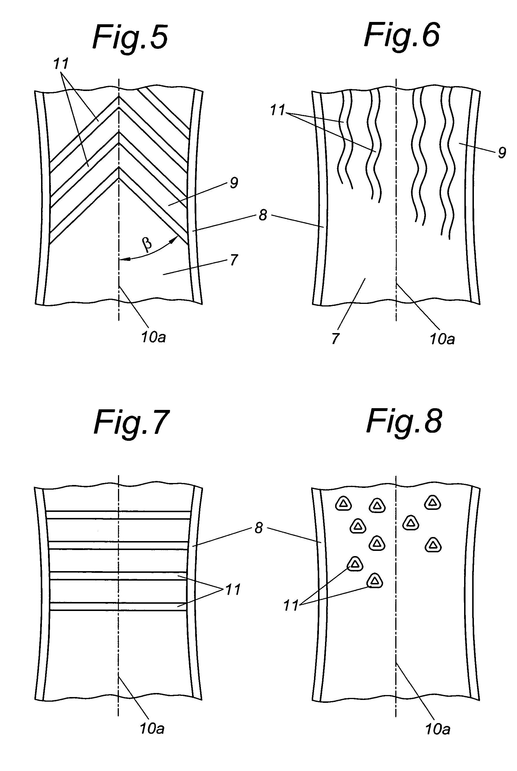
[0013] Especially advantageous gliding properties are achieved when the tool is moved at least in sections at a predetermined angle relative to the longitudinal direction of the track blank. If this angle concerns a right angle, the produced grooves extend transversally to the riding direction, which offers advantages in certain snow conditions. It is also possible to provide wave patterns, with both embodiments offering advantages over the known arrangement of longitudinal grooves on the track surface which are caused by the process.
[0014] An especially advantageous variant of the method in accordance with the invention is characterized in that the machining process on the track blank comprising the plastic deformation occurs prior to the application on the winter sports appliance. Guiding the method in such a way has a number of advantages. On the one hand, it is possible to work on plane base which will not curve in the longitudinal direction like an assembled ski and which is not pre-tensioned. A further advantage of this method variant is that it is not necessary to take into account any steel edges when machining the track. The track blank will be cut to size precisely before and after the machining and fit snugly into the recess between the steel edges. Preferably, the machining occurs on a coordinate table, which is a working appliance in which a tool can be moved like a plotter in the longitudinal and transverse direction over the workpiece.
[0017] It is especially advantageous for the gliding properties in this connection when the structure is formed as a groove structure with even depth. It has further proven to be advantageous when the surface structure is composed of predetermined geometrical patterns. Chemical changes to the running surface can be avoided in such a way that the surface structure is produced by chipless machining.
[0019] The machining output can be improved in an especially advantageous manner in such a way that several tools are provided on the tool guide for simultaneous machining of the running surface of the track blank. This allows machining a ski track as in conventional processes simultaneously over its entire width without losing the advantages as described above. It is especially advantageous in this connection when the individual tools are held in a resilient manner independent of each other. This ensures that each individual tool can adjust optimally to the respective local fluctuations in thickness. Other solutions are also possible as an alternative to the above, e.g. a hydraulic bearing of the individual tools. An optimal adjustment of the surface structure to the respective required gliding and riding properties of the winter sports appliance can occur in an especially preferred manner in such a way that the tool guidance comprises a control unit for producing predetermined patterns on the running surface of the track blank.

Problems solved by technology

The reason is that the individual parties in the friction such as the track, snow and interposed water film are difficult to describe and are changeable.
The production and machining of running surface materials made from ultrahigh-molecular polyethylene is difficult because this material cannot be extruded and is extremely difficult to deform.
On the one hand, it is hardly possible to achieve an even surface roughness as a result of unavoidable thickness tolerances in the production of the track blanks because the thickness tolerances are larger than the depth of the structure to be produced.
It is thus unavoidable that the surface properties such as roughness depth depend on the locally present thickness fluctuations of the track blank and are thus uneven and not reproducible.
A further disadvantage of grinding methods is that as a result of the unavoidable local heating of the running surface undesirable chemical changes occur which have an adverse effect on the gliding properties.
Moreover, chemical interactions may occur between the grinding material and the running surface material, leading to a further impairment.
Such embossing methods meet increasing difficulties with increasing molar mass of the track because a plastic deformation is only possible within very strict limits as a result of the reduced flow characteristics.
In addition, the above-mentioned irregularities occur as a result of the thickness tolerance because the local pressure of the embossing tool on the surface of the track is influenced very strongly by the thickness fluctuations in the track itself.
As a result of these facts, it is hardly possible with such a method, especially in the case of high-molecular running surfaces, to produce reproducible surface structures.

Method used


Image

  • Method for machining the running surfaces of winter sports appliances
  • Method for machining the running surfaces of winter sports appliances
  • Method for machining the running surfaces of winter sports appliances

Examples


Embodiment Construction

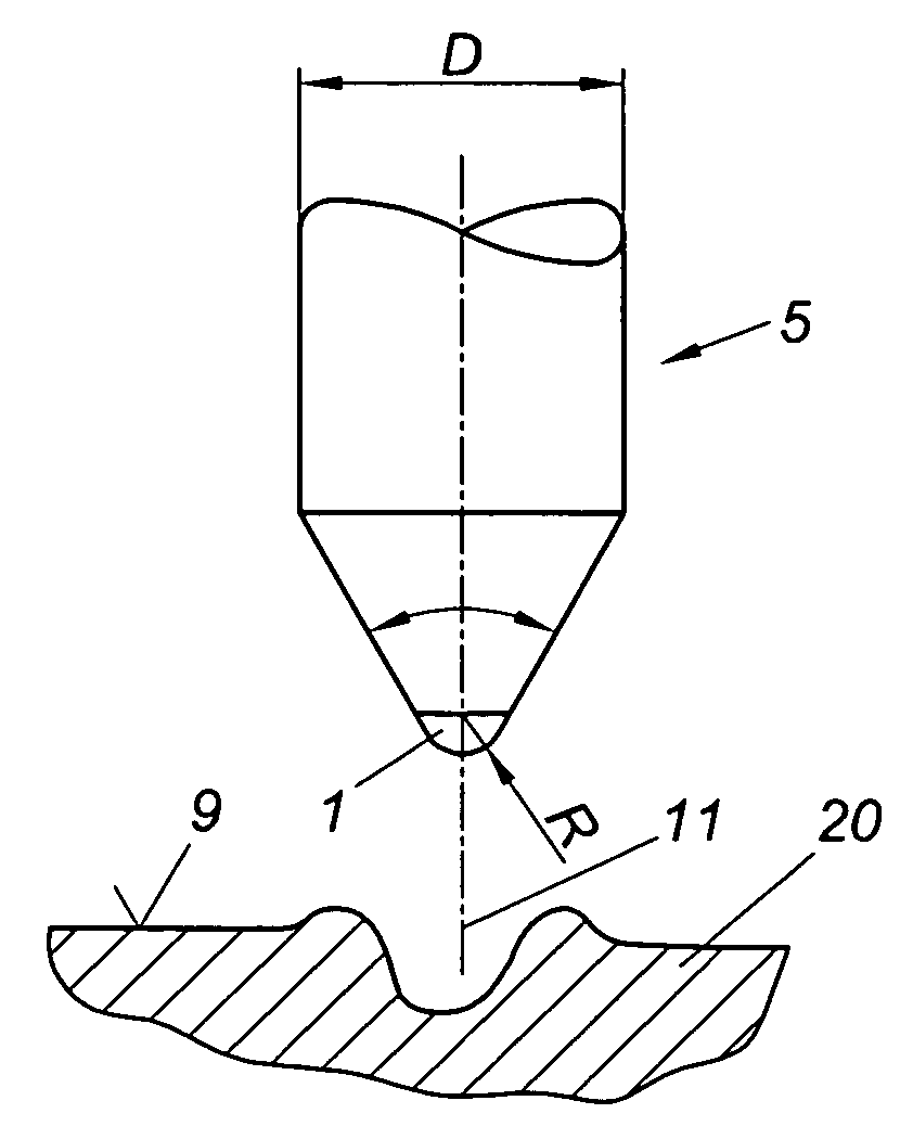
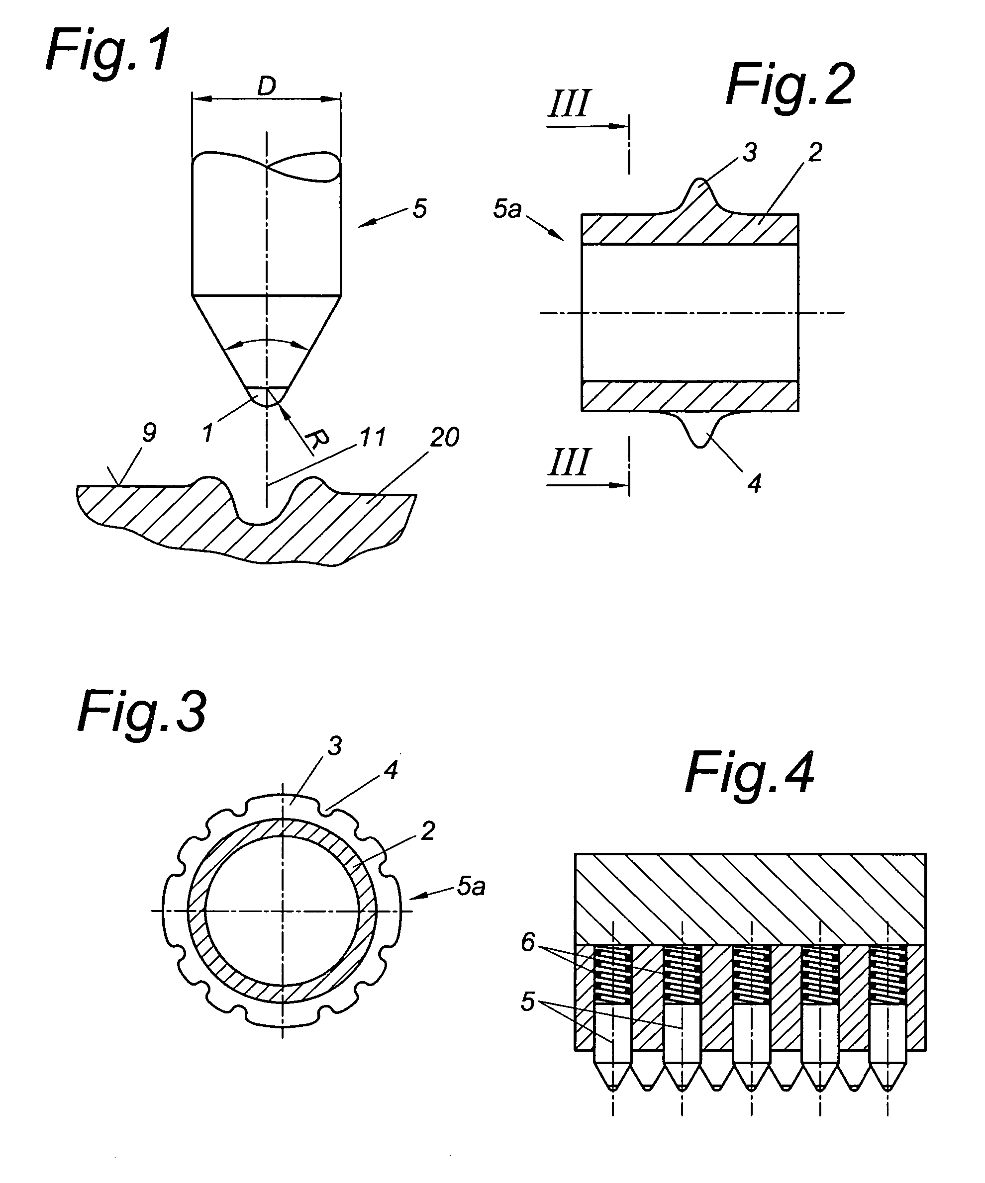
[0027] The tool of FIG. 1 concerns an engraving diamond 5 with a shaft diameter D of 3 mm for example, a cone angle α of 60° and a radius R of the diamond tip 1 of 0.02 mm. The track blank is indicated with reference numeral 20.

[0028]FIG. 2 shows a cutting wheel 5a which consists of a cylindrical main body and a circumferential projection 3. FIG. 3 shows that the projection 3 comprises interruptions 4 which are distributed along the circumference.

[0029]FIG. 4 shows a multiple tool in which several diamond pins 5 are displaceable adjacent to one another in the longitudinal direction and are each pre-tensioned by a spring 6. Further pins are arranged with a gap in between behind the pins 5 of the first row in order to enable producing a higher groove density.

[0030]FIG. 5 schematically shows a section of a ski 7 with an exaggerated sidecutting. The steel edges 8 delimit the running surface 9. A plurality of grooves 11 is arranged at an angle p relative to the longitudinal axis 10a, ...


PUM


Abstract

The invention relates to a method for machining the running surfaces (9) of winter sports appliances such as skis or snowboards, in which a blank track (20) is subjected to a machining process in order to obtain a predetermined surface microstructure which improves the gliding ability. A precisely defined and reproducible surface structure of the track is achieved in such a way that the machining process for producing the surface microstructure comprises a plastic deformation by a tool (5, 5a) which is moved over a running surface (9) of the track blank (20) and is pressed with a predetermined force on the track blank (20) in order to deform the same in a plastic manner. The invention further relates to a winter sports appliance which is produced with such a method and an apparatus for performing the method.

Description

BACKGROUND OF THE INVENTION [0001] The invention relates to a method for machining the running surfaces of winter sports appliances such as skis or snowboards, in which a blank track is subjected to a machining process in order to obtain a predetermined surface microstructure which improves the gliding ability. DESCRIPTION OF PRIOR ART [0002] The gliding of a winter sports appliance such as a ski on snow represents a special kind of a frictional case. The reason is that the individual parties in the friction such as the track, snow and interposed water film are difficult to describe and are changeable. It is known that the frictional resistance can be positively influenced under certain circumstances by a purposeful roughening of the surface of the respective object under conditions as are present in skis, but also other conditions such as relate to boats and aircraft. One reason for the improved gliding properties of rough surfaces of the running surface materials of skis lies in t...

Claims


Application Information

Patent Timeline
Patent Type & Authority Applications(United States)
IPC IPC(8): A63C5/00B23C9/00
CPCA63C5/0428Y10T409/30532A63C5/044
Inventor SCHAMESBERGER, ROBERT
Owner ATOMIC AUSTRIA
Learn More