Horizontal register transfer pulse generation circuit and imaging apparatus

a technology of horizontal register and pulse generation circuit, which is applied in the direction of color television details, television system details, television systems, etc., can solve the problems of poor transfer, difficult to expand the control range, and difficult to maintain phase relationships constant, so as to reduce poor transfer

Inactive Publication Date: 2006-11-02
SONY CORP
View PDF9 Cites 2 Cited by
  • Summary
  • Abstract
  • Description
  • Claims
  • Application Information

AI Technical Summary

Benefits of technology

[0033] As described above, in the horizontal register transfer pulse generation circuit of the present invention, even if arbitrary phase adjustment is carried out, the horizontal register transfer pulse can be generated which cannot be easily influenced by the variations in the phase-adjusted output signal resulting from the phase adjustment. Further, when adopting the drive system of three or more phases, the mask start timing can be changed according to each horizontal register transfer pulse, so that poor transfer can be reduced.

Problems solved by technology

Incidentally, when performing phase adjustment by means of such a delay element, as described above, it is difficult to expand a control range, because an amount of delay which can be adjusted is influenced by a circuit scale.
Further, it is difficult to maintain phase relationships constant, because of the influence of variations resulting from a manufacture process, a supply voltage, an operating temperature, etc.
Further, the generation of the conventional horizontal register transfer pulse may cause poor transfer when the horizontal register employs a drive system of three or more phases.

Method used


Image

  • Horizontal register transfer pulse generation circuit and imaging apparatus
  • Horizontal register transfer pulse generation circuit and imaging apparatus
  • Horizontal register transfer pulse generation circuit and imaging apparatus

Examples


Embodiment Construction

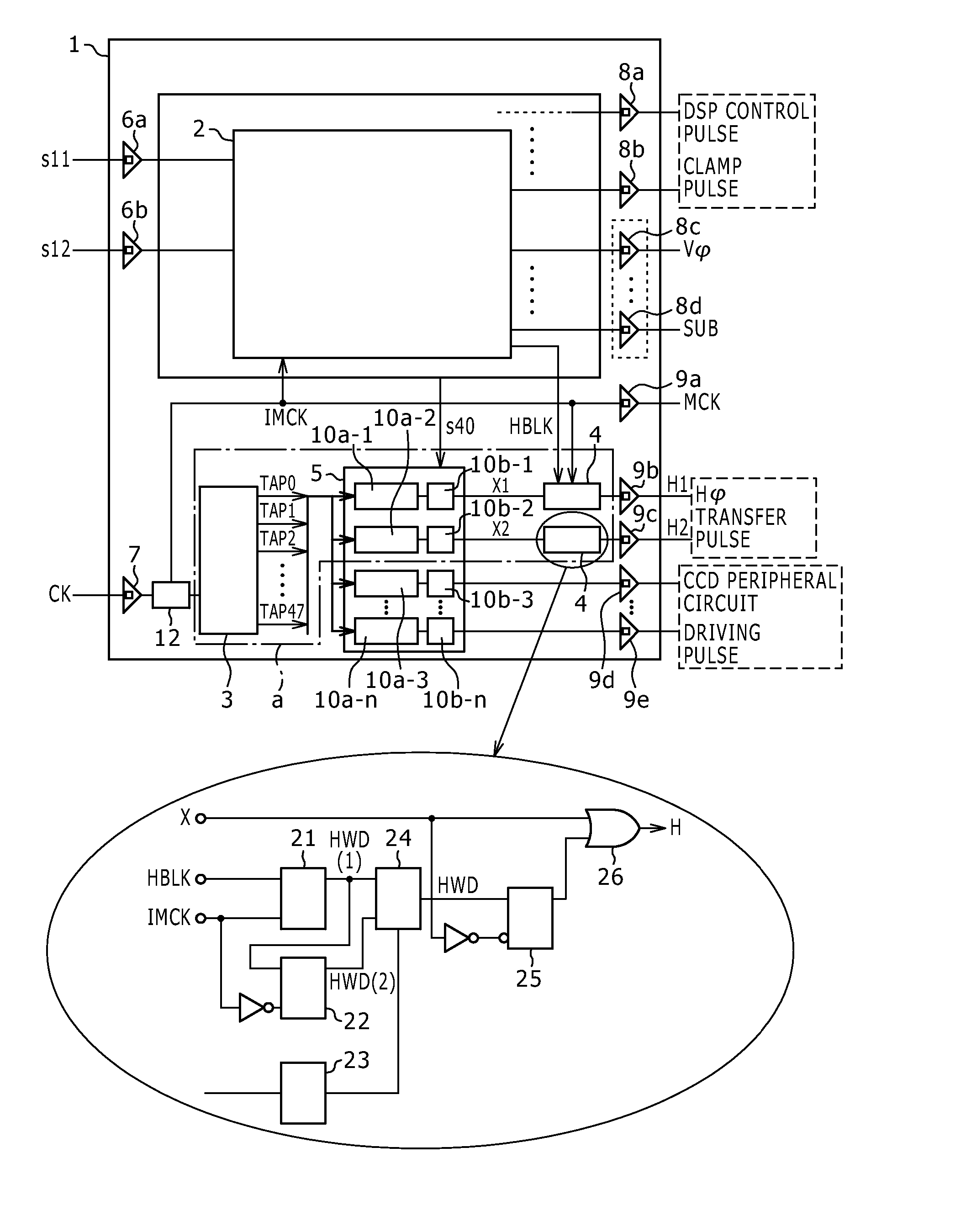
[0042]FIG. 1 is a schematic block diagram for explaining a horizontal register transfer pulse generation circuit to which the present invention is applied. A horizontal register transfer pulse generation circuit as indicated by reference “a” in FIG. 1 is provided in a timing generator circuit 1 built in an imaging apparatus which has a CCD solid state imaging device.

[0043] In addition, references 6a, 6b, and 7 in FIG. 1 respectively indicate input buffers, and references 8a, 8b, 8c, 8d, 9a, 9b, 9c, 9d, and 9e are output buffers, respectively.

[0044] In this timing generator circuit, as with the conventional timing generator, the synchronizing signal s11 in synchronism with other circuits (not shown) and the control signal s12 are arranged to be inputted through the input buffers 6a and 6b respectively. The inputted synchronizing signal and the control signal are arranged to be processed in a signal input / output control unit 2 which is constituted by a logic circuit.

[0045] As with ...


PUM


Abstract

A horizontal register transfer pulse generator includes: phase adjuster generating an output signal, from reference signal; and horizontal blanking period generator based on output signal, reference signal, and horizontal blanking pulse, wherein horizontal blanking period generator includes: delay masking pulse generator generating delay masking pulse delayed by predetermined phase relative to masking pulse generated on horizontal blanking pulse inputted into horizontal blanking period generator; and determination means determining phase difference between output signal and reference signal, when phase difference between output signal and reference signal is less than predetermined phase, horizontal blanking period generator combines masking pulse with output signal to generate horizontal register transfer pulse with horizontal blanking period, and when phase difference between output signal and reference signal is equal to or greater than predetermined phase, horizontal blanking period generator combines delay masking pulse with output signal to generate horizontal register transfer pulse with horizontal blanking period.

Description

CROSS REFERENCE TO RELATED APPLICATIONS [0001] The present application claims priority to Japanese Patent Application JP2005-132130 filed in the Japanese Patent Office on Apr. 28, 2005, the entire contents of which being incorporated herein by reference to the extent permitted by law. BACKGROUND OF THE INVENTION [0002] 1. Field of the Invention [0003] The present invention relates to a horizontal register transfer pulse generation circuit and an imaging apparatus, in particular relates to a horizontal register transfer pulse generation circuit which generates a horizontal register transfer pulse used for driving a horizontal register of a CCD (Charge Coupled Device) type solid state imaging device, and an imaging apparatus having a CCD solid state imaging device which has such a circuit. [0004] 2. Description of the Related Art [0005] Conventionally, an imaging apparatus having a CCD type solid state imaging device transfers electric charges accumulated in each photo diode to each v...

Claims


Application Information

Patent Timeline
Patent Type & Authority Applications(United States)
IPC IPC(8): H04N5/335H04N5/341H04N5/357H04N5/369H04N5/372H04N5/376
CPCH04N5/335H04N25/00
Inventor TAGAMI, HIROYASUINOUE, MASAHIROYAMAMOTO, HIDEKI
Owner SONY CORP
Why Eureka
Try Eureka