Lamp arrangement with a lamp and a base

a technology of lamp and base, which is applied in the direction of incadescent cooling arrangement, discharge tube main electrode, light and heating apparatus, etc., can solve the problems of unfavorable lamp operation, high temperature increase, unduly high temperature increase, etc., and achieve the effect of avoiding the need for lamp operation before it is too la

Inactive Publication Date: 2008-06-10
USHIO DENKI KK
View PDF9 Cites 1 Cited by
  • Summary
  • Abstract
  • Description
  • Claims
  • Application Information

AI Technical Summary

Benefits of technology

[0011]A primary object of the invention is to devise a lamp which is provided with a base with a long service life in which the feed components of the base are prevented from being overheated and oxidized and in which premature cessation of lamp operation is avoided.
[0016]Additionally, the object is achieved in that the heat insulator is formed by the wall thickness of the lamp holding part being locally reduced.
[0020]The lamp with a base in accordance with the invention yields the following effects:
[0021]Even if the heat from the hermetically sealed portion is transferred to the lamp holding part of the base which is located on the hermetically sealed portion of the lamp, or even if the lamp holding part is heated by the light which has been emitted from the lamp, the heat is poorly transferred to the bottom of the base since a heat insulator is formed in which the amount of heat transferred in the axial direction of the base is less than elsewhere. Thus, a temperature increase of the feed components is prevented.
[0022]As a result, it becomes possible to prevent the feed components at the base from exceeding the heat stability temperature. Thus, the contact state between the feed components and the feed connecting parts of the base can always be kept in the optimum state without oxidation of the feed components, and a lamp which is provided with a base with a long service life without cessation of lamp operation can be achieved.

Problems solved by technology

However, for semiconductor production, since the amount of light emitted by the filament of the above described lamp is very large, the frame and the socket are heated by the light to a high temperature, by which there is no longer a temperature gradient between the feed pins, the socket and the frame.
There is the disadvantage here that the heat of the feed pins is not dissipated via the socket to the frame.
The feed pins cause an unduly high temperature increase, by which they are oxidized before their service life expires; this has many highly adverse effects on the lamp.
If the feed pins are being oxidized, between the feed connecting parts in the socket and the feed pins, the value of the electrical resistance is always set to a high value; this causes a temperature increase of the hermetically sealed portion and of the socket of the lamp and a reduction of the lamp efficiency which ultimately leads to cessation of lamp operation.

Method used


Image

  • Lamp arrangement with a lamp and a base
  • Lamp arrangement with a lamp and a base
  • Lamp arrangement with a lamp and a base

Examples


embodiment 1

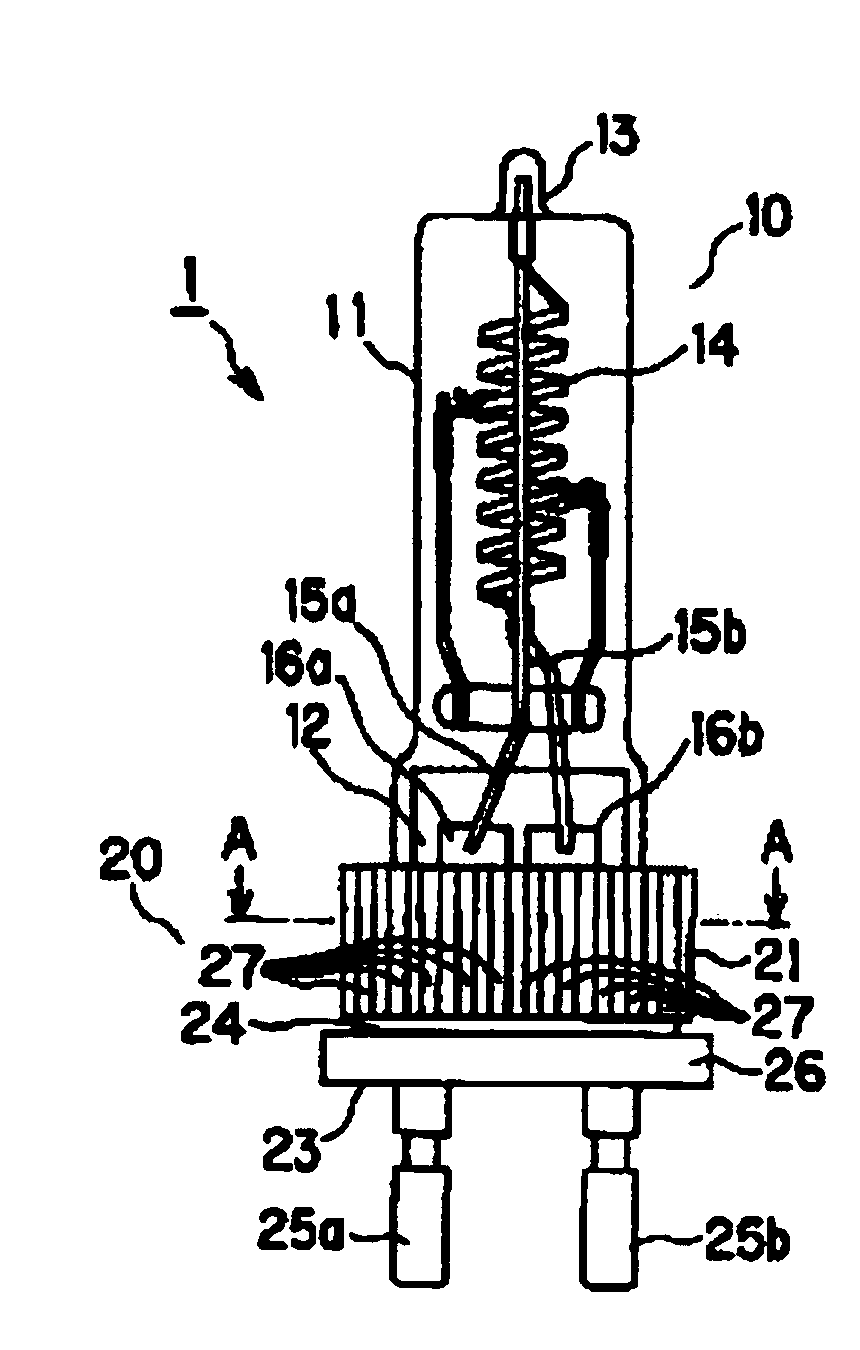
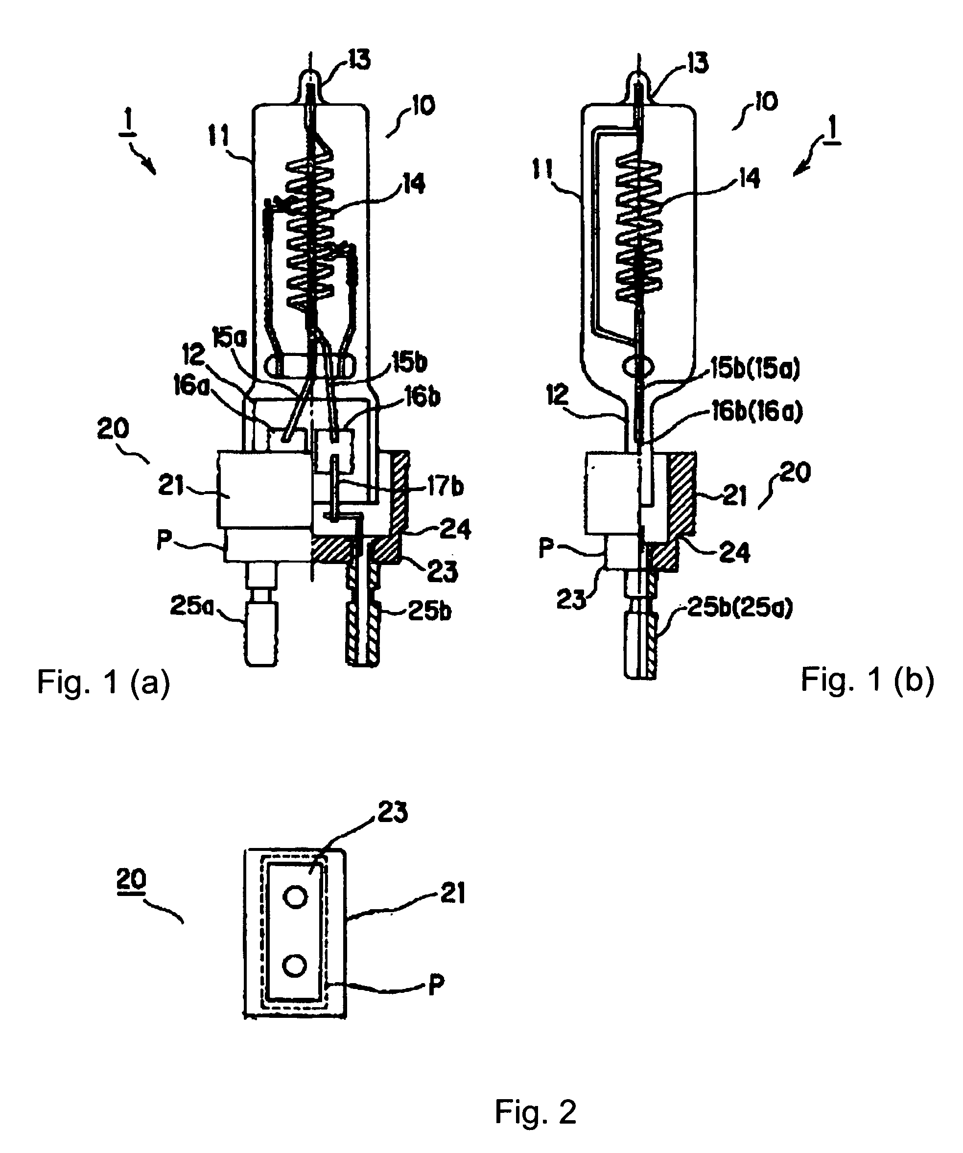
[0048]One embodiment of the lamp with a base of the invention is described below. A lamp provided with a base according to the first embodiment of FIGS. 1(a), 1(b) &2 was produced under the conditions described below.

(Filament Lamp)

[0049]Arc tube: material: silica glass[0050]total length: 150 mm[0051]outside diameter: 27 mm[0052]inside diameter: 25 mm[0053]Filament: material: tungsten[0054]Total length of light emitting part: 25 mm[0055]Inner lead pin: material: tungsten[0056]Metal foil: material: molybdenum[0057]Filler: krypton gas, nitrogen and halogen compound[0058]Rated voltage: 120 V[0059]Rated power consumption: 500 W

(Base)[0060]Insulator part: material: aluminum oxide[0061]total length: 50 mm[0062]Opening in the lamp holding part: 13 mm×35 mm[0063]Thickness of the lamp holding part: 6 mm[0064]Thickness of the heat insulator: 2 mm

embodiment 2

[0065]Without changing the specification of the filament lamp according to the above described embodiment 1, a lamp provided with a base according to embodiment 2 with the arrangement shown in FIGS. 3(a) &3(b) was produced. This means that the base according to the embodiment 2 has the same basic arrangement and the same dimensions as the base described in embodiment 1. Furthermore, here, the bottom of the base is provided with a heat radiation part with an enlarged diameter.

(Base)

[0066]Outside diameter of the heat radiation part: 46 mm[0067]Length of the heat radiation part in the axial direction of the base: 4 mm

embodiment 3

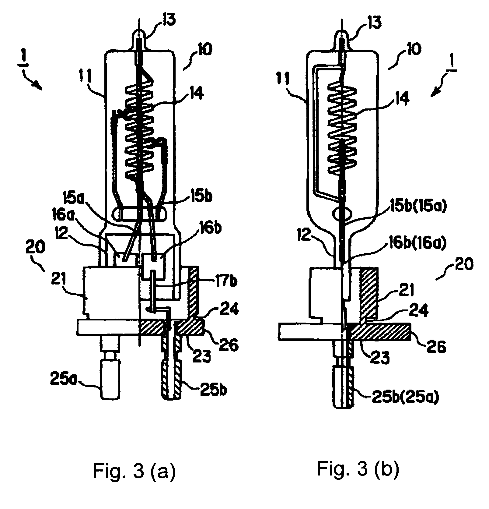
[0068]Under the conditions described below, a lamp provided with a base according to embodiment 3 with the arrangement described in FIGS. 4(a), &4(b) was produced.

(Filament lamp)

[0069]Arc tube: material: silica glass[0070]total length: 150 mm[0071]outside diameter: 27 mm[0072]inside diameter: 25 mm[0073]Filament: material: tungsten[0074]Total length of light emitting part: 34 mm[0075]Inner lead pin: material: tungsten[0076]Metal foil: material: molybdenum[0077]Filler: krypton gas, nitrogen and halogen compound[0078]Rated voltage: 120 V[0079]Rated power consumption: 2000 W

[0080]The base according to embodiment 3 has the same basic arrangement and the same dimensions as the base in the above described embodiment 2. Furthermore, the lamp holding part of the base is provided with a host of radiating fins.


PUM


Abstract

A lamp arrangement with a lamp and a base which is located on a hermetically sealed portion of the lamp. The base comprises a hollow cylindrical lamp holding part which holds and secures the hermetically sealed portion of the lamp, a bottom which borders the lower end of the lamp holding part, which end faces away from the lamp; and feed components which project from the back end face of the bottom, which end face faces away from the lamp. Between the lamp holding part and the bottom, a heat insulator is formed in which the amount of heat transferred in the axial direction of the base is less than the amount of heat transferred away from the base.

Description

BACKGROUND OF THE INVENTION[0001]1. Field of the Invention[0002]The invention relates to a lamp with a base on a hermetically sealed portion of the lamp.[0003]2. Description of the Prior Art[0004]A technique is known in which the light source for heating a semiconductor wafer is a filament lamp in which there is a base on a hermetically sealed portion. The semiconductor wafer is irradiated with light which contains IR radiation, and the temperature of the semiconductor wafer is thus quickly raised to a given temperature. This filament lamp with a base if formed, for example, essentially of a filament lamp with a so-called one-sided sealed termination in which, on one end of the arc tube, a hermetically sealed portion is formed, and of a ceramic base which holds the hermetically sealed portion of this filament lamp. By an arrangement of a host of filament lamps with a base on a frame on which there are a host of sockets next to one another, they are formed and used as a heating unit....

Claims


Application Information

Patent Timeline
Patent Type & Authority Patents(United States)
IPC IPC(8): H01J5/48H01J5/54H01J5/50
CPCH01K1/18H01K1/46
Inventor YAMAMIZU, YUTAKAMURAKI, SHINOBU
Owner USHIO DENKI KK
Why Eureka
Try Eureka