Process for the preparation of an olefin polymerisation catalyst

a polymerisation catalyst and polymer technology, applied in the field of olefin polymerisation catalyst preparation, can solve the problems of inhomogeneity of the resulting catalyst, catalyst support on external carriers has its drawbacks, and the polymer properties are not easily available, so as to achieve easy and economical operation, without any loss in catalyst quality and amoun

Active Publication Date: 2012-07-17
BOREALIS TECH OY
View PDF22 Cites 0 Cited by
  • Summary
  • Abstract
  • Description
  • Claims
  • Application Information

AI Technical Summary

Benefits of technology

[0014]Due to the several common and more specific problems of the batch-wise catalyst preparation processes there is a need for improved processes for preparing olefin polymerization catalysts, especially for solid olefin catalysts, which are not supported on an external carrier, which processes lead to uniform catalyst particles and thus to uniform polymers having desired morphology. In particular there is a need for processes which can be operated easily and economically also in commercial scale essentially without any losses in catalyst quality and amount.
[0029]One of the main advantages of the invention is, as mentioned above, that the detrimental transfer of the emulsion having a limited stability can be avoided. Further, the preparation steps can be run in constant conditions. Any changes in physical conditions or chemical concentrations in the reactors in a continuous process are independent of time, which again supports the formation of desired homogeneous products. Further, smaller reactors can be used due to the improved hold-up volumes.

Problems solved by technology

Further, single-site catalysts (e.g. metallocenes) have been used and have been found to afford polymer properties not easily available by using ZN catalysts.
However, even the catalysts supported on external carriers have their drawbacks.
The main drawbacks concern the inhomogeneity of the resulting catalyst.
From the point of view of catalyst and polymer properties, one of the most important drawbacks of this kind of heterogeneous catalyst system is that it is difficult or even impossible to get solid catalyst particles, wherein the catalyst components are evenly distributed through the catalyst support.
Furthermore, the inhomogeneity problem also exists between catalyst particles, i.e. intra and inter particle inhomogeneity problems occur.
Thus, any variations in catalyst distribution and morphology lead to differences in catalytic behavior in polymerisations and result in inconsistencies in the polymer product.
In addition, use of an external support involves additional costs, the quality of the support must be carefully controlled, and still sometimes carrier residues might cause some problems.
However, the use of batch reactors causes problems in the resulting catalysts due to variations in the concentration of different components and in the physical conditions in the reactors with time.
In addition there are inconsistencies between the different batches prepared.
Moreover, in a batch process, the reactor volumes have to be large if catalysts are to be prepared on a commercial scale.
In the production of solid catalyst supported on an external carrier by a batch process there are also some additional problems.
The process of this publication is, however, still far from a continuous process since it only describes a continuous method by which only one part of one step of the preparation of MgCl2 based ZN catalyst can be carried out.
However, the batch-wise processes disclosed in the above references cause additional problems in the above process and furthermore in the produced catalyst as well.
Firstly, the process requires the transfer of the emulsion between two reactors.
Because the stability of the emulsion is very limited, such transfers and any possible storage needed in between transfers will result in loss of material quality and amount.
In a batch-wise process, during the solidification, temperature and solvent concentration vary with time and thus temporal differences occur meaning that individual particles are exposed to different environments, which again leads to catalyst with undesired non-uniform particles and having uneven chemical composition distribution within the particles.
Hence the end products obtained using such catalysts are of decreased quality.
In addition to these specific problems, drawbacks of common batch-wise processes relating e.g. to high reactor volumes in commercial production and common non-uniform products exist.

Method used


Image

  • Process for the preparation of an olefin polymerisation catalyst
  • Process for the preparation of an olefin polymerisation catalyst
  • Process for the preparation of an olefin polymerisation catalyst

Examples


example 1

[0115]Complex Preparation

[0116]264 mg of rac-dimethylsilanediyl-bis(2-methyl-4-phenylindenyl)zirconium dichloride (97 wt.-%, purchased from Catalytica Advanced Technologies) were reacted with 20 ml MAO solution, 30 wt.-% in toluene (purchased from Albemarle) under stirring at room temperature in a septa bottle for 30 minutes. A red solution of activated complex (with target Al / Zr=200) was obtained (solution 1).

[0117]Surfactant Preparation

[0118]0.5 ml of 1H,1H,7H-perfluoroheptan-1-ol (Apollo Scientific, UK) were added slowly to 2.5 ml MAO under stirring. A vigorous reaction with liberation of gas occurred. After 15 minutes, an additional 2.5 ml of MAO were added to the solution. No visible reaction was observed while stirring for additional 15 minutes. The resulting surfactant solution was transferred into the septa bottle with solution 1.

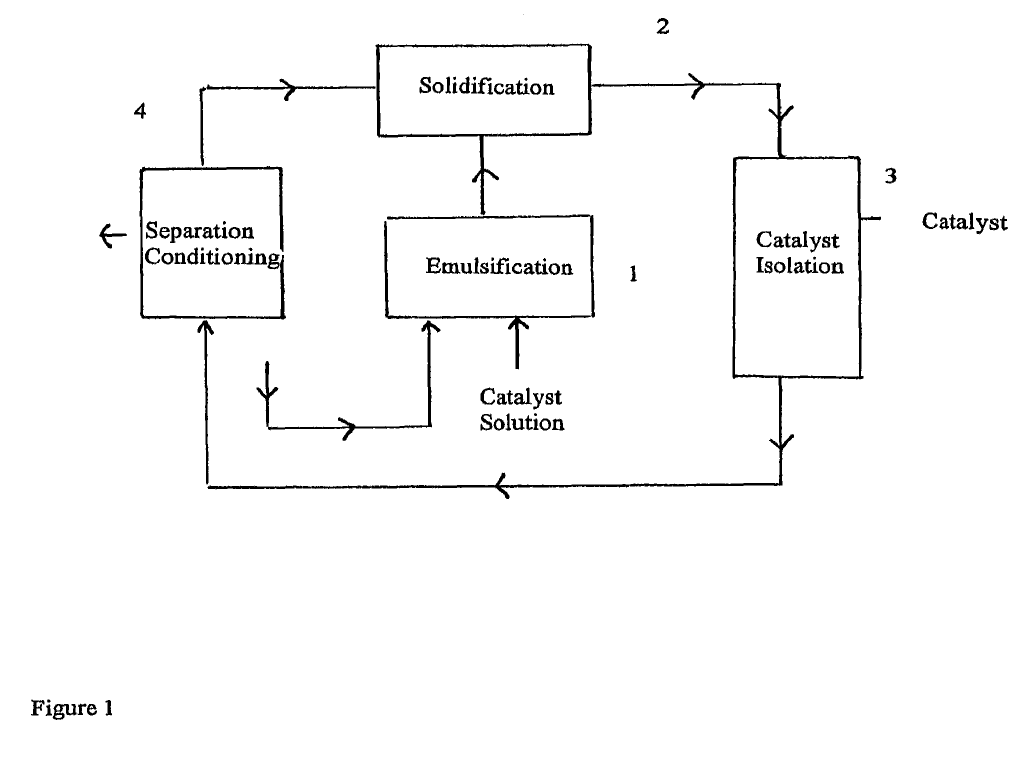
[0119]Continuous Operation

[0120]Emulsification

[0121]As emulsion reactor, a continuous stirred tank reactor (volume approx. 400 ml) made of glass an...

example 2

[0140]The complex and surfactant were prepared as in example 1.

[0141]Continuous Operation

[0142]The process of example 1 was repeated with the exception that some minor changes in temperature were done.

[0143]Emulsification

[0144]The same reactor as in example 1 was used. The temperature in the reactor was adjusted to approx. +4° C. via a cryostat connected to the reactor's cooling jacket.

[0145]The reactor was (partly) filled by pumping cold perfluorooctane from the PFO storage tank.

[0146]Under stirring, the complex / MAO solution mentioned above was added batch-wise to the reactor via a syringe. Emulsification of the two immiscible phases (complex / MAO / toluene and PFO) was done by the rotor-stator mixer operated at 4500 RPM leading to a tip speed of about 4.7 m / s.

[0147]Solidification

[0148]The resulting emulsion was continuously pressed out from the emulsion reactor to a solidification tube via a dip tube by pumping in additional cold PFO from the PFO tank with the pump (flow rate used wa...

example 3

[0164]The complex and surfactant were prepared as in example 1.

[0165]Continuous Operation

[0166]Emulsification

[0167]As emulsion reactor, a continuous working chamber for the rotor stator stirrer (volume approx. 70 ml) made of steel and equipped with a cooling coil attached to chamber wall was used. The reactor was cooled to −10° C. in the cooling coil.

[0168]The reactor was filled by pumping in cold perfluorooctane from a PFO storage tank and complex / MAO solution pumped in continuously from a septa bottle by an additional metering pump.

[0169]Emulsification of the two immiscible phases (complex / MAO / toluene and PFO) was done by the rotor-stator mixer operated at 4000 RPM leading to a tip speed of about 4.17 m / s.

[0170]The emulsification chamber was operated fully filled.

[0171]Solidification

[0172]The emulsion prepared above was continuously pressed out from the reactor to a solidification tube via a dip tube (Teflon, inner diameter 3 mm) and continuously pumping in cold PFO and complex / MA...


PUM

PropertyMeasurementUnit
temperatureaaaaaaaaaa

Abstract

This invention relates to a process for the preparation of an olefin polymerization catalyst, to the use of the catalyst in olefin polymerization and to the catalyst and polymers obtained. In particular, the invention relates to the preparation of a catalyst comprising an organometallic compound of a transition metal of Group 3 to 10 of the Periodic Table (IUPAC) by a semi-continuous or continuous process.

Description

CROSS REFERENCE TO RELATED APPLICATIONS[0001]The present application is a National Phase Application of International Application No. PCT / EP2005 / 013874, filed Dec. 22, 2005, which claims priority to European Patent Application No. 04258193.4, filed Dec. 31, 2004, which applications are incorporated herein fully by this reference.[0002]This invention relates to a process for the preparation of an olefin polymerisation catalyst, to the use of the catalyst in olefin polymerisation and to the catalyst and polymers obtained. In particular, the invention relates to the preparation of a catalyst comprising an organometallic compound of a transition metal of Group 3 to 10 of the Periodic Table (IUPAC), or of an actinide or lanthanide, by a semi-continuous or continuous process.BACKGROUND ART[0003]Many processes and catalysts are known for the preparation of olefin polymers. Ziegler-Natta (ZN) catalyst compositions and chromium oxide compounds have, for example, been found to be useful in th...

Claims


Application Information

Patent Timeline
Patent Type & Authority Patents(United States)
IPC IPC(8): C08F4/602C08F4/6592B01J31/22
CPCC08F10/00C08F4/65912C08F4/65908C08F4/65927C08F110/06Y10S526/943C08F2500/18C08F2500/24B01J37/00B01J37/03B01J35/08
Inventor BARTKE, MICHAELDENIFL, PETER
Owner BOREALIS TECH OY
Why Eureka
Try Eureka